- Home
- EFNOTE MINI
- EFNOTE 5
- EFNOTE 5X
- EFNOTE 3X
- EFNOTE 7
- EFNOTE 7X
- EFNOTE 3B
- EFNOTE PRO 500 - 507
- EFNOTE PRO 700 - 707
- EFNOTE PLAY STATIONS
- EFNOTE FINDER
- Artesia250
- AMPLIFICATION FOR EDRUMS
- BLACK STREET STUDIO
- 2BOX PLAY STATIONS
- 2Box drumIt Three
- 2Box drumIt Five MK II
- 2Box speedlight kit's
- Tdrum black Trigger
- Triggerhead since 1999
- Store
- 2Box Support
- 2Box Editor Software
- 2Box free sound library
- 2Box drumIt Three Anleitung - D
- 2Box drumIt Three Manual - E
- 2Box video tutorials
- Akangatide brushes
- ddrum originaly by Clavia
- Ludwig - pearls from the last century
- Links
- Newsletter
- über uns / about us
2Box drumIt Three - Manuals
2Box drumIt Three - Manual english
Operating system 1.32
Thank you…
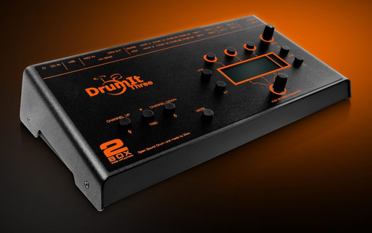
for choosing a 2BOX DrumIt Three module. You have chosen wisely. Your new sound module comes with an open sound architecture and a universal trigger interface. To get up and running with your DrumIt Three module, we recommend taking the time to read this Quick Start manual.
It provides a concise presentation of all functions you need to be aware of and everything you need to know to come to grips with this feature-rich instrument.
Have fun
Contents
1 Intro
2 Important Safety Precautions
3.1 Operation
3.2 Menu structure
3.3 USB mode
3.4 File-System
3.5 User-KIT-Bank and Single-KIT-file
3.6 Channel overview
5 Controls
6 Setting Up and Calibrating The Hi-Hat
8.1 KIT – PROG
8.2 KIT – DRUM*
8.3 KIT – ENV*
8.4 CFUNC*
8.5 KFNC*
8.6 KIT – VOL*
8.7 KIT – EQ
8.8 KIT – ACMP
9.1 UNIT – MIX
9.2 UNIT . CHAN
9.3 UNIT – TRIG*
9.4 UNIT – HCAL
9.5 UNIT – HSET
9.6 UNIT – SPEC
9.7 UNIT – INTF*
9.8 UNIT – OUT
9.9 UNIT – METR
9.10 UNIT – MIDI
9.11 UNIT – PREF
9.12 UNIT – MEM
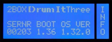
9.13 UNIT – INFO
10 Signal Flow and Routing Options
12 Update
13 FAQs
14 Contact and Support
1 Intro
Thank you for choosing DrumIt Three of 2box. You made the right choice.
Your new instrument combines first-class sound with highest flexibility. The DrumIt Three module has an open sound architecture and offers 15 independent
trigger channels, 4 audio outs and 4 GB sound memory.
Trigger
The DrumIt Three has an ultra-fast and precise trigger interface and allows virtually latency-free playing with a huge dynamical range. Depending on the pads used, several zones are available for triggering different sounds. The snare channel, for instance, supports 3 zones (head, rim, cross stick), the DrumIt Three’s tom channels provide 2 (head, rim) and the cymbal channels 3 (edge, bow and bell). In addition, the cymbal channels feature a “Choke” function that allows drummers to abruptly silence the cymbal sound in the same way as on an acoustic kit.
Sounds
The sounds of the DrumIt Three are convincing through an absolutely natural listening experience. This is achieved by a complex
multi-layer method. Drums and cymbals were recorded at hi-end recording studios with sophisticated multi-miking and at various distances. All sounds were mixed in stereo, some rather “dry” and others with
clearly audible room ambience.
In a 2BOX "multi-layer" every Instrument is recorded at many different volume levels. So, the intensity of a stroke not only affects the volume, but also the sound and frequency response. Some of the factory presets consist of up to 128 ( ) single-layers. The result is an absolutely natural sound performance and an outstanding authenticity of the samples.
You can assign any sound to any drum channel. However, there are instruments with multiple (sound) zones, which are only fully available when they are controlled by a matching pad (for example, cymbal sounds with 3 zones: edge, bow, bell). Each drum sound is saved as a single file and sorted in the respective folders. This way, you keep track of everything and can organize your sounds simple and straightforward.
Memory locations (KITs)
The-DrumIt Three sound module provides 4 GB of sound memory space with 100 presets (KITs). In contrast to common practice, where memory slots are divided into factory-KITs and (blank) user-KITs in DrumIt Three all ( ) KITs are already preconfigured at the factory and can nervertheless be modified and saved according to your needs. Of course you can rename and rearrange KITs to make access and handling on stage easier. Please note that for this, the SAVE mode has to be enabled (see page 59).
Play-Along function
If you like to practice with songs or backing tracks, you can load standard WAV files in CD quality (stereo, 16 Bit/44,1 kHz) into the module via USB and then assign them to a KIT. Alternatively, you can connect a CD or MP3 player to the line-in jack. Of course, you can also use this input for other instruments or a monitor mix (live resp. studio).
Metronome
The built-in metronome not only helps you with practicing and refining your technique, but can also be used for live performances. You can save one individually programmed metronome per KIT. There is a variety of time signatures and sounds available and the tempo can precisely be adjusted according to your specifications. The metronome can as well be used as a one- or two-bar count in: The Click automatically stops in the respective mode.
PC / Mac Editor
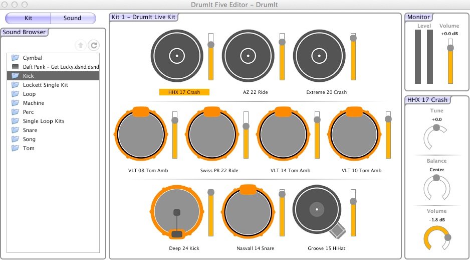
With the DrumIt Three software editor you can easily manage your module from your computer, and even create your own sounds in DrumIt Three format. Once the DrumIt Three module is connected to your computer (Mac or PC) via USB, you can organize and manage the 100 internal KITs. Assign sounds from the extensive internal DrumIt library and make your personal settings (tuning, volume, pan). You can preview the sounds comfortably on the computer and edit settings with ease.
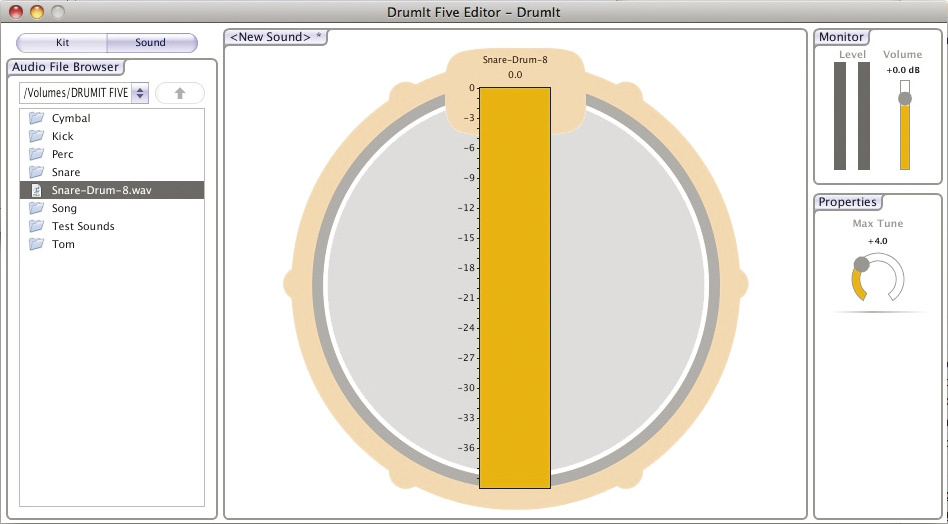
In addition, you can create your own sounds in the specific DrumIt Three format. Create your own multi- layered sound files from WAV files, eg. from recordings of your acoustic set or sounds from sample libraries.
2 Important Safety Precautions
Never try to open or modify the power supply adapter.
· If the power supply is damaged, be sure to purchase a new 2BOX adapter. When
using a third-party adapter, make sure it is a 12V/1000mA DC power supply (100- 240V).
· Never use the power supply outdoors or in damp locations.
· The DrumIt Three module operates at low power and should therefore pose no particular hazard. We nevertheless urge you to operate it in a responsible manner.
· Do not allow any liquids to penetrate inside the unit.
· Never drop the unit.
· Never apply excessive force to the module or its controls.
· Never expose the module to extremely hot (>40°C) or cold (below 0°C) temperatures.
· Avoid covering the module’s bottom or rear panel, or its power supply adapter with blankets and the like. These areas become hot while the unit is in use, and this heat needs to be dissipated in one way or another.
· In short: be sure to handle the DrumIt Three module with the same care as any other electronic device you own. This will ensure maximum enjoyment for years to come.
3 Basic Know-How
3.1 OperationBedienung
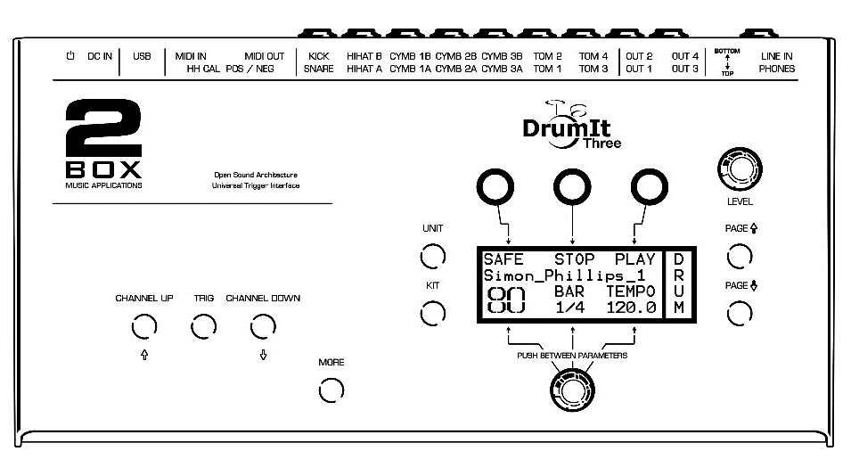
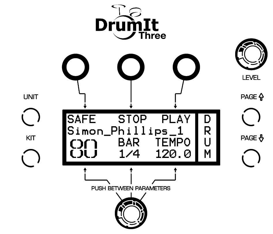
The module’s user interface is highly intuitive and based on two menu items (UNIT and KIT), each with a number of parameter pages. The parameter pages can be selected sequentially using the PAGE UP and PAGE DOWN buttons. There are no secondary levels or hidden menu items.
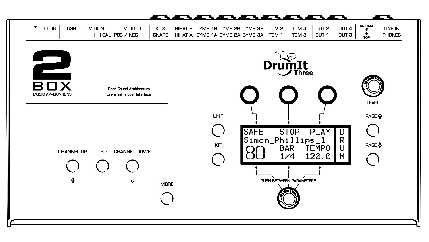
The main page comprises six logical areas. The three DATA buttons above the display are assigned to the values or functions that appear in the top row. Press the button above the desired entry to set values or select functions.
The three entries in the bottom row are controlled using the rotary knob below the display. This knob can be used to set the value of the parameter that is currently selected. To select a different parameter in the bottom row, simply press the knob. The flashing entry refers to the parameter that is currently selected. Hold MORE and press the knob to toggle between alternative parameters indicated by an arrow.
3.2 Menu structure
The DrumIt Three module is characterized by a simple and intuitive menu structure. There are two general operating modes:
UNIT: In the mode UNIT, you make general settings for your module.
KIT: in the mode KIT you will find all pages that you need to edit a KIT. A “KIT” is a set, factory made or edited resp. programmed by you, that contains all drum channel, sound, effect, tempo and song settings and is stored on one of the 100 program memory locations.
Each mode has a number of pages, on which the various functions are grouped thematically. There are pages that contain global settings and others that allow separate settings for each drum channel. The latter are indicated by * in the chapter heading and the table of contents.
Scroll through the respective menu with PAGE ▲ or PAGE ▼ to select the desired page.
3.3 USB mode
When you connect the DrumIt Three module via USB to your computer (PC or Mac) and run it in USB mode, it will be recognized and displayed as a "normal" memory drive. The module now behaves exactly like an external USB hard drive or a card reader. You can e.g. exchange, move and copy the sound files by drag & drop between your computer and your 2BOX module. This makes the management of 2BOX sounds as easy and straightforward as working with digital photos, MP3s or Office files.
In order to start the DrumIt Three module in USB mode, simply hold down the left DATA button above the display, while powering up the unit.
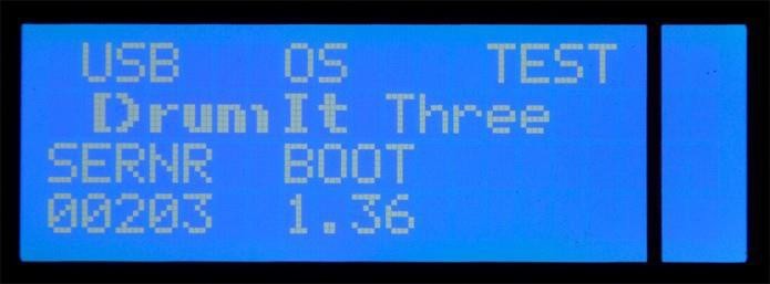
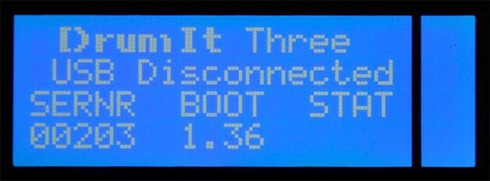
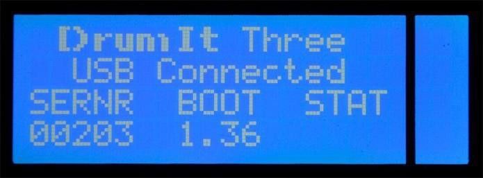
The display now looks as follows:
No USB connection
Active USB connection
When the module is correctly connected to the computer, "R" (below "Stat") symbolizes read mode and "W" write mode. Please note that errors may occur in the file system when you disconnect the USB cable while the module is in read (R) or write mode (W).
Backup
When your DrumIt Three module is connected to your PC via USB, you can easily save the content of the module so as to prevent accidental loss of your sound files.
Copy the uncompressed files to your computer or use a conventional back-up program.
3.4 File-System
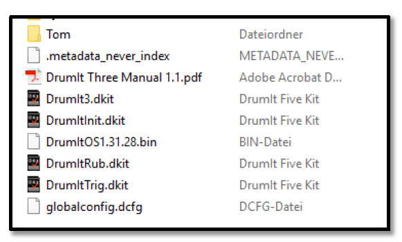
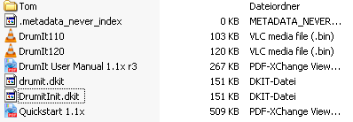
At the root level, you will find the following files:
DrumIt3.dkit
Standard User KIT Bank. This file contains your own KIT and UNIT settings.
DrumItInit.dkit
This file contains the KIT and UNIT settings programmed at the factory. This file is required to perform a factory reset of the unit.
DrumItRub.dkit
A User KIT Bank optimized for 2box Pads
with Rubber Heads.
DrumItTrig.dkit
A User KIT Bank optimized for 2box TrigIt Triggers.
DrumItOS1.3x.xx.bin
Firmware (operating system) of the DrumIt Three.
DrumIt Three x.x.pdf Manuals in the PDF format.
globalconfig.dcfg Index file, which is required for Mac operating systems.
.metadata_never_index System file.
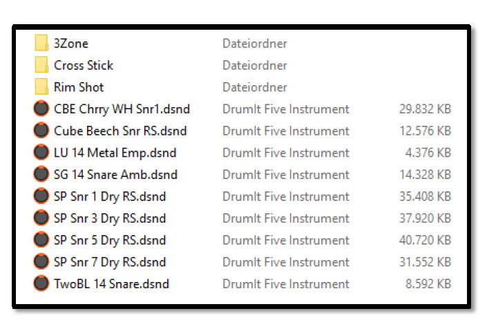
The folders contain the 2BOX sound files in the DSND format as well as play-along songs in the WAV format.
Feel free to change the folder structure so as to organize the files in a way that works for you. Given the DrumIt Three module’s display size, we recommend using short folder names and working with a limited number of folder levels.
Connect your DrumIt Three module to a computer and save your files with a back-up
program or by simply copying via
drag and drop.
3.5 User-KIT-Bank and User-KIT-file
User-KIT-Bank
The user-KIT-bank (drumit.dkit)) contains 100 KITs (program memory locations), which are already filled with a variety of factory preset KIT setups. All 100 KITs can be changed freely by you and then stored if necessary. Please note that for this the SAVE mode has to be enabled (see page 59).
Multiple user KIT banks
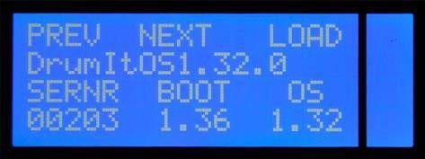
It is even possible to have multiple user KIT banks. Just copy the drumit.dkit file to your module and rename the file according to your ideas. Now there are 2 user-KIT-banks with 100 editable user KITs each available To switch between the user-KIT-banks, you have to select the respective bank when starting the module. To do this, hold down the KIT button when the unit is powered up. In the menu that now appears, you can choose between the various user KIT banks (PREV and NEXT) and then open the desired KIT bank (OPEN).
Switching the KIT bank
By pressing the MORE and the KIT button for 2 seconds you will enter a menu where you are able to switch to another KIT Bank. At next power up, DrumIt Three will start with the last chosen KIT Bank.
3.6 Channel overview
The table below provides basic information about the functions of the DrumIt Three module.
|
Drum-Channel |
Trigger-Channel |
MIDI-Note |
Zone |
Choke |
|||
|
1 |
4 |
8 |
9 |
||||
|
KICK |
KICK |
C2 |
Head |
- |
- |
- |
|
|
SNARE |
SNARE |
F2 |
Head |
- |
- |
- |
|
|
PERC 5 |
F#2 |
- |
- |
Rim |
- |
|
|
|
HIHAT |
HIHAT |
A2-A#2-B2 |
- |
Bow |
Edge |
Foot |
|
|
TOM 1 |
TOM 1 |
D3 |
Head |
- |
- |
- |
|
|
PERC 1 |
D#3 |
- |
- |
Rim |
- |
|
|
|
TOM 2 |
TOM 2 |
F3 |
Head |
- |
- |
- |
|
|
PERC 2 |
F#3 |
- |
- |
Rim |
- |
|
|
|
TOM 3 |
TOM 3 |
A3 |
Head |
- |
- |
- |
|
|
PERC 3 |
A#3 |
- |
- |
Rim |
- |
|
|
|
TOM 4 |
TOM 4 |
C4 |
Head |
- |
- |
- |
|
|
PERC 4 |
C#4 |
- |
- |
Rim |
- |
|
|
|
CYMB 1 |
CYMB 1 |
E4-F4-F#4-(G4) |
Bell |
Bow |
Edge |
- |
X |
|
CYMB 2 |
CYMB 2 |
B4-C5-C#5-(D5) |
Bell |
Bow |
Edge |
- |
X |
|
CYMB 3 |
CYMB 3 |
E5-F5-F#5-(G5) |
Bell |
Bow |
Edge |
- |
X |
Drum-Channel
A Drum Channel is synonymous with the connectivity options of the module (see also page 14). The HIHAT and CYMBAL 1~3 channels have 2 connectors—A and B. Input A receives pad signals, and input B optional control signals (HH Control, Bell Control).
Trigger-Channel
The DrumIt Three module provides 10 connectors for pads (i.e. drum channels). But there are up to 15 independent trigger channels available, since five of the drum channels are designed as Dual-Channels (SNARE, TOM 1 to TOM 4). These additional trigger channels are referred to as PERC 1 to PERC 5 (see table) and can be edited like the other drum channels. The additional channels can be controlled via both MIDI and pads.
MIDI-Note
The table shows the MIDI notes that are assigned to the individual trigger channels at the factory. Of course these settings can be changed individually (see also page 52).
There is a special feature on the Drum Channels HIHAT and CYMB 1 to 3 (highlighted in gray in the table). Each MIDI note controls one zone resp. the choke function (in the table marked by ()).
Here's an example:
CYMB 1: E4 = bell, F4 bow, F#4 = edge, (G4) = choke function
The four MIDI notes are grouped together and can not ( ) be changed individually. Only the first MIDI note can be edited (see page 52). The other MIDI notes are linked to the first note. The notes are always successive half-steps. If e.g., the MIDI note of the Drum Channel CYMB 1 (see example above) is changed from E4 to G4, the MIDI notes of the other zones automatically change accordingly.
CYMB 1: G4 = bell, G#4 = bow, A4 = edge, (A#4) = choke function
Please make sure that there is no overlap with other channel settings.
Zone
Similar to an acoustic instrument that sounds different depending on where it is played, there are sound areas, called zones, which, depending on the type of drum channel (e.g. TOM, CYMB), have different sounds assigned to. The various types of Pads feature in turn playing areas (zones), corresponding to the respective (sound) zones.
Please note that you may not be able to use all of the sounds when you connect a pad in which the playing zones do not match the zones of the drum channel. For example, if you use a tom pad on a CYMBAL channel, you will not be able to trigger all sounds.
Trigger-Channel PERC 1 to PERC 5
To edit a PERC Channel, you have to hold the MORE button while you press the TRIG button
If there is no sound assigned to a PERC channel, the rim sound of the associated trigger channel is used automatically.
Example:
|
Situation |
Trigger channel |
Assigned sound |
Zone |
|
|
1 |
8 |
|||
|
No sound assigned to the PERC-Channel |
SNARE |
Maple_10_Snare |
head sound "Maple_10_Snare" |
rim sound "Maple_10_Snare" |
|
PERC 5 |
- |
- |
- |
|
|
With sound assigned to the PERC channel |
SNARE |
Maple_10_Snare |
head sound "Maple_10_Snare" |
- |
|
PERC 5 |
Bobs 1950 cowbell |
- |
sound "Bobs 1950 cowbell" |
|
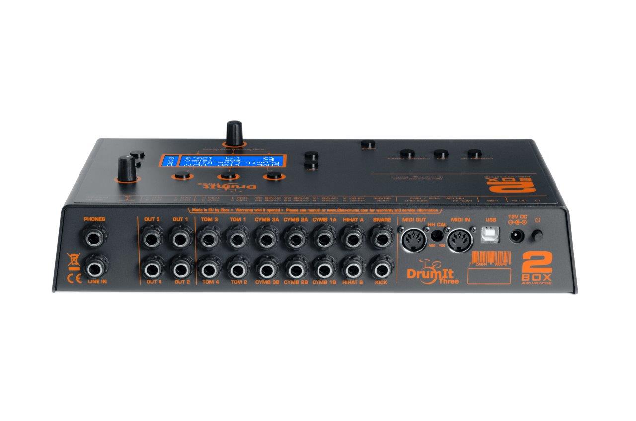
4 Connections
This module provides the following inputs and outputs:
USB
This port lets you connect the module to a computer (PC or Mac). The USB port on the DrumIt Three is a 1.1 port (full speed - 12 Mbit/s) and compatible with USB 1.1 and USB 2.0. The DrumIt Three module is designed as a standard USB mass storage device and requires no driver installation. Once the module is connected to the computer and started in USB mode, it is immediately recognized as an external storage drive. You can now handle the module like an external hard drive or a USB stick.
12V DC This is where you connect the external power supply.
MIDI IN Connect this to the MIDI OUT socket on the external MIDI controller to allow the module to receive MIDI messages.
MIDI OUT Connect this to the MIDI IN socket of the device that should receive MIDI messages from the module.
Channels
Connect your pads to the inputs that correspond to the instrument you wish to trigger. The hi-hat controller needs to be connected to the HIHAT B socket. The B channels of CYMB 1~3 are intended for pads that accommodate 2 stereo cables. Given that all inputs are balanced (stereo), be sure to only connect stereo cables.
OUT 1~4
These are the DrumIt Three’s outputs, which can be connected to a mixer or amplifier. By default, OUT1 and 2 transmit the mixed stereo signal. OUT3 and 4, on the other hand, are assigned to BUS3 and BUS4 respectively. If necessary, OUT 1 and 2 can also output BUS signals (BUS1 and BUS2). This can be set on the UNIT-OUT page.
PHONES
Plug your headphones into this 1/4" stereo phone jack (recommended impedance 32 Ω - 600 Ω). Adjust to the desired volume with the LEVEL control LEVEL control right above the display.
LINE IN
This is where you can connect an external signal source. You can use a stereo cable (for your smartphone, for instance) or a mono cable (e.g. to listen to the monitor signal via the DrumIt Three in a live setting). If you plug in a mono cable, the audio signal is only heard in the „center“, when you select "mono" on the page OUT in the menu UNIT (see also page 55). Please note that the factory default setting of the LINE IN volume is set to “0” in the MIX. To hear LINE IN you will need to raise the value.
Connector Assignment
All pads are connected with stereo jack cables. The trigger signal for the main zone is always on the tip of the plug, the signals of other zones or controllers are on the ring.
Additional Trigger-Channels
It is possible to use an additional five trigger channels (PERC 1 to 5) to increase the number of pads connected to the DrumIt Three module from 10 to a total of 15 pads.
In order to be able to use the additional trigger channels, connect two pads with a Y-splitter cable (1 x stereo jack to 2 x mono jack) to the SNARE or the TOM channel. Here, the stereo plug is inserted into the module and the two mono plugs into the pads.
Important If you connect the pads this way, you can only use the main zone (e.g. head) and will lose all other trigger signals (e.g. rim).
For example, you connect two pads to a TOM channel as described above. On both pads only the head sensor works, but no longer the rim sensor. On one side you lose ... the rim as a trigger source, but on the other hand, you gain an additional playing area, to which you can assign a sound of your choice.
5 Controls
CHANNEL UP / CHANNEL DOWN
The CHANNEL UP and CHANNEL DOWN buttons on the left are used to select the drum channels sequentially for editing, etc. To see which channel is currently selected, take a look at the “UNIT CHAN” page. Alternatively, channels can be selected simply by hitting the assigned pad. To switch to the selected channel’s Trigger channel (PERC 1~5), press the MORE and TRIG buttons simultaneously.
TRIG Button
Press the TRIG button to audition the sound assigned to the selected channel. Press MORE+TRIG to select the associated Trigger channel (rim).
MORE Button
With the MORE button you can access the additional trigger channels (PERC 1 to 5 - see above). You also need the MORE button for additional functions and operational steps (such as undo / redo, see page 25).
With the help of the MORE button you can e.g. call up the most recently visited edit page in the modes UNIT or KIT. For this, hold down the MORE button and press UNIT or KIT. Now the display will automatically jump to the last page you were on (for example KIT VOL, or UNIT TRIG) and you do not have to scroll through the entire menu again.
If you hold down the MORE button, you can use the DATA buttons to call up parameter values in reverse order – i.e. backwards.
UNIT Button
This button takes you to the "UNIT" mode and the corresponding pages. In the UNIT menu, you make settings of parameters that affect the entire DrumIt Three system and apply globally to all KITs (e.g. mixer, trigger, MIDI and general pad settings).
KIT Button
Pressing this button, you enter the "KIT" mode with the corresponding pages and change the respective KIT settings. When switching on the module, the KIT-mode is already.
DATA Button
These three buttons are used to stepwise change the parameters that are displayed in the upper two rows of the display below. Examples: saving of settings, undo / redo steps, start / stop commands for the metronome respectively the media player).
DATA Controller
This knob can be used to set the value of the parameter that is currently selected. To select a different parameter in the bottom row, simply press the knob. The flashing entry refers to the parameter that is currently selected. Hold MORE and press the knob to toggle between alternative parameters indicated by an arrow
LEVEL Control
This control adjusts the overall volume of the module. By default, this affects both the headphone output and the main outputs OUT1 and OUT2; but in the menu the latter can be uncoupled from the LEVEL control, so that your output always has a fixed level (see page 55 UNIT – OUT).
PAGE Button
Use these buttons
to move through
the respective menus (UNIT or KIT).
Display
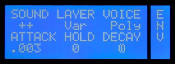
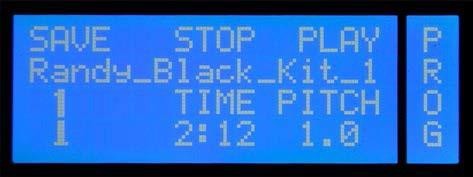
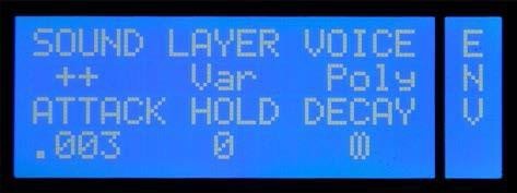
The display of the DrumIt Three-module can give a readout of up to 6 parameters. In general, these are three below the DATA buttons and three above the DATA controllers. The name of the parameter is always in the upper row (see example: SOUND, LAYER, VOICE, ATTACK, HOLD, DECAY) and the value to be edited beneath (see Example: ATTACK = .003).
However, there are pages in which the value extends over several
fields. However, from the context it is obvious what it is about. In the example
below, the entire second row is used for the KIT-name
and the KIT number
is displayed without a heading.
In addition, on some pages not all the buttons / controllers have a function assigned. On the page MIDI (see example below) two of the three controllers have no function.
6 Setting Up and Calibrating the Hi-Hat
The hi-hat is the most complex instrument of your drum kit. The DrumIt Three module has been designed to accommodate a vast number of hi-hat pads and controllers of several manufacturers. This flexibility, however, also means that there are a number of parameters that need to be set to take advantage of the DrumIt Three’s full potential. In most instances, these setup and calibration steps only need to be performed once.
Just follow the steps below to set up your hi-hat within minutes.
1. Connect the hi-hat pad and optional hi-hat controller (if available) to the corresponding inputs on the module. Input A is to be used for the trigger signals while Input B is to be used for the control commands.
2. Navigate to the UNIT-HCAL page. Remember that this page is only displayed while the hi-hat channel is selected. Use the CHANNEL buttons to select the hi-hat channel or simply hit the hi-hat pad.
3. Next, specify the hi-hat type you connected.
DEF All popular hi-hat types and brands
2BOXHH 2BOX DrumIt Five Hi-hat
ALEHH Alesis Crimson hi-hat controller
4. Set the RAW value so that it matches the connected pad. Use a screwdriver to change the setting of the recessed screw (HH Cal) on the module’s back panel. The values below are merely indications of what might work for you. Feel free to tweak the setting to adapt the response to your playing style.
| Yamaha | 850-900 |
| Roland | 800-850 |
| Alesis | 830-880 |
| 2BOX | 600-650 |
5. Start the calibration process:
5.1. Press the leftmost DATA button once. A closed hi-hat icon appears in the display and starts flashing.
5.2. Close the hi-hat pad or press the controller’s pedal with your foot.
5.3. Press the leftmost DATA button a second time. An open hi-hat icon appears in the display and starts flashing.
5.4. Open the hi-hat pad or remove your foot from the pedal.
5.5. Press the leftmost DATA button yet again to exit the calibration function.
5.6. The display shows “done”. The hi-hat has been successfully calibrated. If the message “NoChg” is displayed instead, the calibration could either not be performed or was repeated with the exact same settings. If the calibration routine failed, start by repeating steps 1~4 and then calibrate your hi-hat again.
6. If the calibration was successful, you can now check whether the hi-hat responds to your playing as expected. If you are not happy with the response, either repeat the calibration steps or fine-tune the following parameters.
PFACT Increase this value to raise the calibration threshold. This is useful for a consistent “foot chick” (pedaled hi-hat) and “foot splash” (quick release of the pedal after a chick) sound. We recommend taking your time to find the setting that you are most comfortable with.
POFF This parameter allows you to change the hi-hat’s calibration range: higher values extend the range, while lower values narrow it down. Bear in mind that changing this setting also affects the PFACT setting. We recommend editing this parameter only once you are thoroughly familiar with the system.
Note: When using a 2BOX pad, the function of the two parameters is exactly inversed.
7. Another important aspect is the hi-hat channel’s trigger response. This can be set using the relevant menu items (see the downloadable User Manual for details).
UNIT-TRIG This is where you set the hi-hat pedal’s response and sensitivity. Set the main parameters (GAIN, THRES, CURVE) to match your playing style. The most important of these is GAIN. Set it so that only the most forceful strikes produce a Level value of 0.0.
UNIT-HSET This page is used to set the hi-hat pedal’s sensitivity/level (SENS) and its dynamic response (CURVE).
This completes the hi-hat settings
7 Menu Structure
UNIT Menu
The UNIT menu contains settings that apply to the module as a whole. This means that they affect all KITs (presets).
MIX: This is where the internal mixer is located. The mixer allows you to set and balance the levels of all channels/instruments.
CHAN: This is where you can select trigger channels for editing (although you can also select trigger channels simply by hitting the corresponding pad).
TRIG: This is where you will find the main trigger settings for each channel.
Here are a few examples: What pad type did you connect? How responsive should the pad be? Which dynamics curve best matches your playing style?
It would be a good idea to take some time to familiarize yourself with these settings. We are confident you will be impressed by the DrumIt Three module’s responsiveness once all settings are in place.
HCAL*: This is where you set up your hi-hat and calibrate the corresponding pad. See below and the User Manual for a detailed discussion of these settings.
HSET*: This page is used to fine-tune the settings you made on the HCAL page. Use it to ensure the response matches your playing style.
SPEC: This page allows you to set aspects that help you avoid double triggering and cross-talk. This is especially important for acoustic drum triggers you may be using.
INTF: This page is used to specify the MIDI and routing settings for each individual channel. Here you can select MIDI channels, route the signals to the mixer and assign the required channels to DIRECT OUTs.
OUT: This page allows you to set the output routing. Which signals should be assigned to the MAIN outputs (OUT 1 and 2) and which to the PHONES connector?
METR: This is where you select the sound of the built-in metronome.
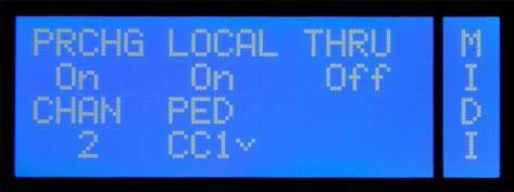
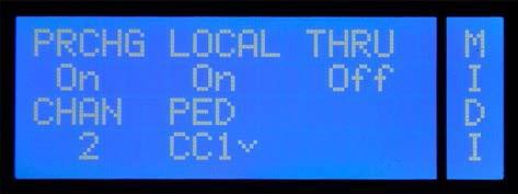
MIDI: This page allows you to set global MIDI parameters. Should the module respond to program change messages, and which control change messages should the hi-hat transmit? These settings are important for recording MIDI data with your computer.
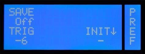
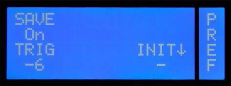
PREF: This page is used to manage the SAVE function and to reset the module to its factory defaults.
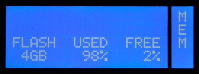
MEM: This is where you can check the remaining memory capacity for additional sounds.
INFO: This page displays the firmware’s version number.
* (only available after
selecting the hi-hat channel)
KIT Menu
The KIT menu allows you to manage and edit the internal memory slots. The module comes with 100 factory KITs (memory slots). Those KITs can be edited and overwritten with your own settings.
The KIT menu allows you to assign the desired sounds to the selected KIT, to edit their settings, to configure the metronome and playback functions and to adjust the built-in equalizer.
PROG:
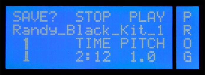
The KIT home page allows you to select a KIT and to start/stop the built-in metronome or song player.
DRUM:
This page is used to assign a sound to the selected drum channel and to set the tuning and volume.
The channel can be selected using the CHANNEL buttons (left) or simply by hitting the assigned pad.
Note: The Rim channels of toms 1 through 4 and the snare (PERC 1~5) can be selected by simultaneously pressing the MORE and TRIG buttons.
ENV:
This is where you fine-tune the selected sound and specify the loop setting for each channel.
CFNC:
If you like, you can also assign a function to a pad rather than a sound. Doing so would allow you to start and stop the metronome, or to select the next KIT by hitting such a pad.
KFNC:
The HHPOS function on this page allows you to set the hi-hat’s opening level (“bashiness”) without recalibrating the pad. This is especially useful if the left foot is used for something else (like double bass drum playing, for instance).
VOL:
This is where you set the level and stereo placement (pan) of the selected channel.
EQ:
Each KIT is equipped with a 3-band equalizer. It can either be applied to all instruments or just for a specific channel.
ACMP:
This page contains the built-in
player. Use it
to specify whether you wish to
play to a song or the built-in metronome. The
metronome’s settings and the tempo can be customized and saved.
8 Saving Your Settings
Any changes you make can be saved internally.
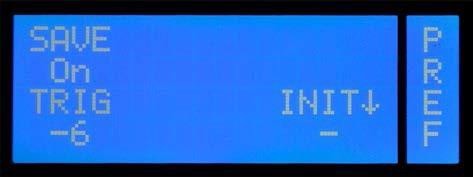
Important: Your settings can only be saved after unlocking the SAVE function in the UNIT-PREF menu (you only need to do so once). Press the leftmost DATA button to switch the SAVE function “On”.
Saving one KIT
Changes you wish to keep after editing the settings on a KIT page require that you save the KIT in question.
If the settings of selected KIT no longer correspond to the stored version, a “?” symbol appears next to
SAVE on the KIT home page.
Press the leftmost DATA button above the display.
Pressing the button above SAVE yet again will write your changes to the selected KIT.
Renaming a KIT
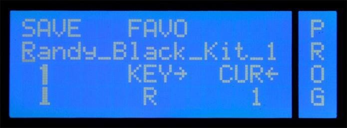
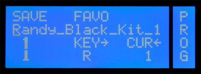
To rename a KIT, press the button above SAVE on the KIT home page.
You can use uppercase and lowercase letters, numbers as well as several special characters for the names you enter. Use the knob to select the desired character (KEY flashes) or hold down the MORE button while pressing the knob to insert a space. Press the knob without holding down the MORE button to select the CUR parameter. Now, the knob can be used to move the flashing underline cursor to another position you want to edit.
Holding down the MORE button while rotating the knob towards the right allows you to insert new spaces. Rotating it to the left in this state deletes the character at the cursor position. To confirm the name, press the leftmost DATA button above the display (SAVE).
Copying, Moving and Swapping KITs
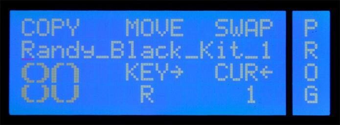
Existing KITs can be moved (MOVE) to a different memory slot, swapped with other KITs (SWAP) and copied (COPY).
Start by pressing the leftmost button above the display.
Rotate the knob to select the number of the KIT that should act as target for the currently selected KIT. After specifying the new KIT number, you can select among three functions: COPY, MOVE and SWAP.
Pressing the leftmost DATA button allows you to copy the selected KIT to the target memory. MOVE allows you to move the KIT towards the target memory (the KITs at and behind this position move one slot). SWAP, finally, causes the two selected KITs to change places. In this example, KIT no. 1 moves to memory 80, while the settings of KIT no. 80 move to memory location 1.
If you like, you can rename the settings during the COPY, MOVE or SWAP operation.
Saving Your UNIT Settings
When you change a setting in the UNIT menu, a “?” appears next to SAVE. Press the leftmost DATA button to save the changes if you want to keep them. The “?” disappears and your changes will be remembered. Please be aware that this is only possible if SAVE mode on the PREF page has been switched on. If the “?” doesn’t disappear after pressing the leftmost DATA button, the SAVE function is currently disabled.
Canceling the SAVE Process
To cancel the save process and exit the SAVE menu, simply press the KIT button. The changes you made remain valid, as the „?“ next to the SAVE option in the menu indicates, but are not stored.
Dismissing Changes
If you decide not to save the changes you made, there are two ways to cancel the settings: Simply select, without saving, another KIT, and the changes are lost.
The UNDO / REDO function offers another possibility.
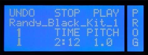
If you press the MORE button before you save, an UNDO function comes up in place of the SAVE function. If you select UNDO, the changes will be reset, but stay cached.
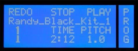
If you press the MORE button once again, you get a REDO option. With this, you can restore your changes.
UNDO/REDO
The UNDO / REDO function is a great way to compare new settings with the original KIT. This feature allows you to switch back and forth between two KIT variants. This way, you can check simply and easily e.g. during a sound check whether the new toms work with the band sound or not.
The various PAGES of the menu are explained in the following. To access these, scroll with the PAGE ▲ and PAGE ▼ buttons to the right of the screen.
Please note that some menu pages affect the whole KIT, while others change the settings for a single drum channel. To make clear at which pages you can make settings for single drum channels, the respective sections are marked as follows:
* = Page
with settings for single
drum channels within
a KIT
8.1 KIT – PROG
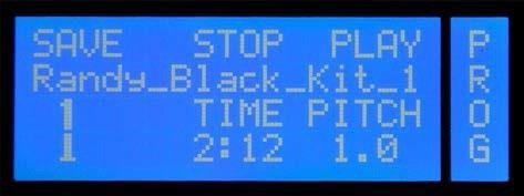
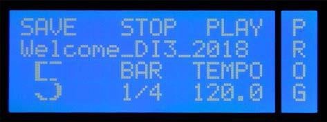
NUMBER The large numeral indicates the KIT number. Use the rotary control to select a KIT (program location).
SAVE See detailed descriptions on page 21.
PLAY/PAUSE PLAY starts - if available – the song or metronome loaded with the KIT (see also page 38). Do this with the DATA button to the right.
When you have started a song with PLAY (Right DATA button), the display changes to PAUSE. With PAUSE (right DATA button again), you can pause the song. The time display below TIME will flash, signaling the PAUSE status.
After assigning the metronome to this KIT you can use the right DATA button to “tap” the tempo. The metronome speed (TEMPO) is calculated automatically based on your taps. The tap functionality can also be assigned to a pad (see the “KIT CFUNC” menu).
STOP Stops playing back the song or the metronome (DATA button in the middle)
Functions for KITs with a Song:
TIME Shows the elapsed time of the song. If no song is selected, "-" appears in the display.
(The knob has no function)
PITCH This feature allows you to change the tempo of the song. You can adjust the tempo in a range between .50 and 1. This feature is useful for playing back the song slower while practicing. Please note that this also changes the pitch.
Functions for KITs with Metronome:
BAR Indicates the selected metronome setting. While the metronome is running, you can read the current bar and the current beat here. (The rotary control has no function)
TEMPO Here you can see or edit the current tempo of the metronome. The metronome has a tempo range from 30 to 280 bpm. When you push the rotary control while holding the MORE button, an arrow appears pointing to the right and you can set the tempo in decimals. If you push the controller once more, you can change the tempo in whole bpm steps again.
Saving the Tempo
The tempo of the metronome is stored with the selected KIT. If you want to change the tempo and keep this change, you have to save the KIT (SAVE).
This function is useful for preparing several tempos for a live performance, which you can recall in succession by selecting the respective KITs.
STOP ALL
With the key combination MORE + STOP (DATA button in the middle) you stop the playback of all sources at once (song, metronome, loops).8.2 KIT – DRUM*
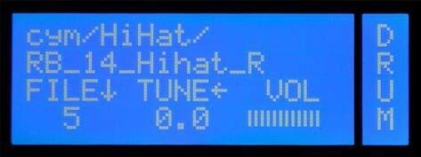
FILE¯/FOLD Here you can assign a sound to a channel. The name of the sound is displayed in the second row. The first row contains information about the folder (category of sounds). Turn the DATA controller to browse the sounds. The FILE-number indicates the position within the selected folder and is not part of the sound name.
If you press the rotary controller while holding the MORE button, the display switches to FOLD ↑. Now you can navigate the folders with the rotary controller. Pressing it again switches back to the FILE ↓ mode. Should a deleted sound be assigned to the channel, a „?“ is displayed instead of the FILE number.
With the three DATA buttons you can trigger the currently selected sound. Each button triggers a different zone, depending on the sound. With a cymbal sound, for example, you can preview Bell, Bow, and Edge, with a kick sound, of course, only the sound of the head.
TUNEß TUNE changes the pitch of the sound. The lowest pitch is at -12 (12 semitones = one octave down). The highest achievable tuning value. Usually it is about four half-steps up (+4). But there are sounds that are can be changed more respectively less than 4 half- steps up. If you press the rotary control while holding the MORE button, you switch to a fine-tuning mode. Then you can adjust the pitch in decimal steps.
VOL With the rotary control you set the volume of the sound resp. the trigger channel. Changing this parameter will automatically affect the VOL value on the KIT-page VOL (see Section 9.4), which is identical with this here.
Please note that the volume of the channel
set here affects both the volume in the mixer and the volume in the selected BUS (see also page 63). I.e.: Increasing the volume of this channel increases the volume of the single output
(selected BUS) and the volume in the corresponding mixer channel at the same time. This in turn affects the sum and/or the
headphone volume.
Selecting a Channel
To select a channel for editing, you can either hit the corresponding pad or select it using the CHANNEL UP and CHANNEL DOWN buttons.
8.3 KIT – ENV*
SOUND
Here you can specify which zone of the selected sound will be used. Depending on the type of sound, several zones can be controlled. For example, with cymbal sounds, three zones (+ Bell + Bow + Edge) are available, with snare sounds, only two zones (+ Fell + Rim). You change the value by pressing the left DATA button. You will be offered all possible combinations sequentially.
Example 1: tom sound: + + = depending on where you hit the pad (head or rim) - the respectively assigned sound is generated
Example 2: tom sound: - + = no matter where you hit the pad, always the rim sound is generated.
Example 3: cymbal sound: + - - = the sound of the bell is always generated.
This feature is helpful if you want to trigger a cymbal on a pad and assign e.g a crash sound on the rim of a tom pad (additional trigger channel (PERC)) and play the bell or the ride on the head.
Loop-Sounds are an exception. When a loop is selected on the page DRUM, the following parameters are available:
Loop The loop will be played until the pad is struck again (start / stop) - default setting -
Loop Regardless of the velocity, the loop is always played at the maximum level
Solo The loop is played only once.
Solo The loop is also played only once, but with maximum volume.
LG1/.../LG3 There are 3 independent loop groups. These allow you to perform instant switches among loops while performing. Example: Let’s suppose you assigned loop A to the TOM1 channel (for the verses) and loop B to the TOM2 channel (for the choruses). If both loops/channels are assigned to the same group (LG1, for instance) starting loop B will automatically stop loop A. Hit TOM1 to start loop
A. Next, hit TOM2: loop B starts and loop A stops automatically. Obviously, you can also stop the running loop (without starting the other) by striking the assigned pad again.
LG1 /.../LG3 As above, but with a fixed maximum
level.
To avoid double-trigger, in loop mode the threshold is internally raised to -24 dB automatically.
LAYER With LAYER you determine the way each sample layer (volume levels) of the sound will be triggered.
Var: (default setting of most sounds) At random, the module selects a layer which is in the volume range that best matches the trigger-impulse intensity. With this setting, the typical "machine gun effect" is avoided, because even with an identical trigger impulse at the following beat, another sound layer will be used (randomly) and previously generated sound layers can still fade out completely.
Top: Regardless of the velocity, always the "top layer" sound, i.e. the loudest layer is used.
Fix: always the layer matching the trigger
impulse best is used. I.e. with identical trigger- impulse
intensity the same layer is used.
In all three situations the audible volume of the sound corresponds with the intensity of the stroke, only the layer within the sound selected by the module changes. When a loop sound is selected, only "fix" is available.
Custom Sounds
With the 2BOX sound editor you can create custom 2BOX sound files (.dsnd) from your own samples (see separate instructions for the Editor). For custom sounds with only a few layers (1-10 layers) the layer setting "FIX" should be selected for the parameter settings on this page, because otherwise the sound has an unnatural effect.
VOICE The values Poly and Mono are available here. When "Mono" is selected, a sound layer can only sound exactly once and might be truncated.
ATTACK This parameter defines the transient response of the sound. The minimum value "0" defines that the sound starts immediately. A value >0 sets the time until maximum volume is reached.
HOLD With HOLD you determine for how long this maximum volume will sound. Combined with other parameters alienated sounds can be produced this way.
DECAY This value determines how long the underlying sample of the sound will be played back.
With the setting ∞ (infinity), the whole sample will be played back.
Gated Sound
With the parameters HOLD and DECAY you can create "gated sounds" (e.g. gated snare). To do this,
set the HOLD value to
the desired time length
and
a short DECAY time value
Loops
The DrumIt Three can play back loops in various playing modes. Loops can be assigned to any drum channel just like a regular 2BOX sound and thus started and stopped via the pads (see details on page 30).
You can also create your own loops. With the DrumIt Three editor, standard WAV files (e.g. from loop libraries) can be converted to the 2BOX file format (.dsnd). The editor is available on our website as a free download.
When creating your own loops, pay attention to the correct (bar-) length of the wave file. Otherwise, the loop will not play correctly.
The tempo of loops can be edited using TUNE ← on the page DRUM in the KIT menu. Please
note that this also changes the pitch.
The TRIG button can also be used for previewing loops. However, only one second of the loop is played. If you want to hear the entire loop, you have to hold the button for half a second. To stop the loop, hold the button half a second once again.
With the key combination MORE + STOP (DATA button in the middle) you stop all running
loops at once.
8.4 CFUNC*
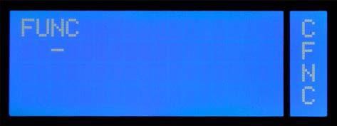
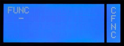
Each DRUM CHANNEL (Pad) can be assigned both sounds and control functions. This is especially useful in a live situation. Press the left DATA button to select the desired function. Hold down MORE while pressing that button to return to the previous function.
- Default setting. The assigned sound is triggered. No function has been assigned.
START Starts the metronome or the built-in song player, depending on which of these two has been selected for the current KIT.
STOP Stops the metronome or song player.
StSto Starts and stops the metronome or song player: the first strike starts it, the second stops it, and so on.
StPau Like StSto, except that song playback is pauses and then continues.
N Kit Selects the following KIT (NEXT KIT).
P Kit Selects the preceding KIT (PREVIOUS KIT).
STPLP Stops all running loops.
Tap Allows you to tap the desired tempo while the metronome is running.
Tap4 A kind of automated count-in: at the 5th strike, the metronome starts with the calculated tempo.
Tap8 Like Tap4, but with 8 strikes.
NONE The trigger channel does nothing.
It neither triggers a sound nor controls a function.
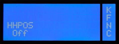
8.5 KFNC*
This page allows you to set the
hi-hat’s aperture. This setting
only applies to the
currently selected KIT. When this value
is
changed, the HH Controller is no
longer available.
This function is useful
when you need a “bashy”
hi-hat sound to accompany double
bass drum parts.
The setting range
is
1 (hi-hat completely open) through 31 (hi-hat
completely closed).
“Off” means that the
hi-hat controller can be
used.
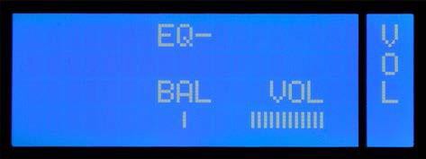
8.6 KIT – VOL*
EQ
This feature allows you to specify whether the signal of the selected drum channel is sent through the EQ (see page 36) (EQ+) or not (EQ-). This feature is only available if the value for BUS on the EQ-page is set to "drum".
BAL
With BAL you determine where the sound is placed in the stereo sound image (left <> right). Please note that the setting affects both the signal going to the internal mixer and the signal on the BUS (individual outputs). If you have for instance a tom routed to BUS 3+4 and now turn BAL all the way to the right, the signal is only on BUS 4, but not on BUS 3.
VOL
With VOL you control the volume of the sound respectively of the drum channel.
If you change the value, this will automatically affect the VOL value on the KIT page DRUM, which
is
identical with this VOL
value here. See also page 29.
8.7 KIT – EQ
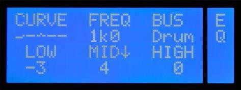
Each KIT is equipped with a 3-band EQ with a semi-parametric mid band.
CURVE Shows you a graphical view of the EQ settings made. Pressing the left DATA button (over CURVE) resets the equalizer. Pressing the button again restores the deleted setting.
FREQ Select the desired frequency for the mid band with the DATA button. Frequencies from 125 Hz to 8 kHz in octave steps are at your disposal. You can also set the desired frequency by using the rotary control. Press the controller and hold the MORE button. The display changes to MID. Now you can fine-tune the cutoff frequency of the mid band with a 1/3-octave equalizer in the range from 100 Hz to 10 kHz.
BUS Select here which signals should be routed to the KIT-EQ. The choices are:
Drum: The drum channels are routed individually through the EQ. Turn on the EQ on the page VOL separately for every channel you want.
Mix: The EQ settings are applied to the internal mixer. All drum channels are automatically routed through the EQ.
Sub: The EQ settings
are applied to the internal SUB-mix and automatically affect all drum
channels that are
routed to the sub-mix.
Live Sound
If you want to process only certain instruments of your KIT with the EQ, e.g. to give the snare a little more mids without changing the tom sound, then select "Drum" as bus setting and turn on the EQ on page VOL only for the snare.
LOW
The low band has a shelf characteristic, the cutoff frequency
is 80Hz. You can cut or boost in
a range from
-12 to +12 dB. In addition, a high-pass filter
at 80 Hz is available.
MID
Here you determine how much the mid band should be boosted or cut (MID¯ -mode). You have a control range from -12 to +12 dB. By pressing the controller while holding the MORE button you change to the MID. Now you can set the desired frequency (see also under FREQ). HIGH Like the low-band, the hi band also has a shelf-characteristic with a cutoff frequency at 12 kHz. Again, you have a control range from -12 to +12 dB and a low pass filter at 12 kHz.
HIGH
Like the low-band, the hi band also has a shelf-characteristic with a cutoff frequency
at 12 kHz. Again, you have a control
range from -12 to +12 dB and a low pass filter at 12 kHz.
8.8 KIT – ACMP
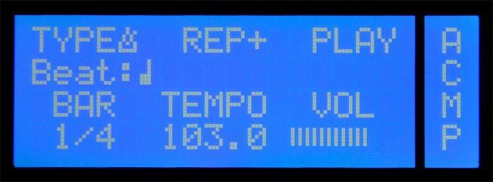
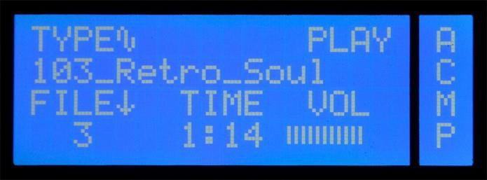
Display view: TYPE song
For live and studio applications, as well as for jamming and practicing, an internal player is provided. The settings you make here are stored in the respective KIT just like sound and equalizer settings. There are two different types of players:
TYPE Choose between the song player and metronome .
PLAY/STOP Use the right DATA button to start or stop the song or the metronome.
VOL This sets the output level
of
the player. Please note that this signal
is sent to the internal
mixer and can be processed
there, too (see also page
41).
Functions for TYPE “Metronome”:
REP REP controls the playback mode of the metronome. REP+ + means that the metronome is playing until you press STOP. With REP1 the metronome plays only one bar, with REP2 two bars. REP1 and REP2 can thus be used as a perfect count-in.
BAR Here you can set the time signature for the metronome. You can choose from a selection of the most important variations with different accents: 1/4, 2/4, 3/4, 4/4, 5/4, 6/4, 7/4, 3/8, 5/8, 6/8, 7/8, 9/8 or 12/8. A setting of 1/4 is recommended if you do not want accents in the click.
TEMPO Here you can set the tempo. There is a tempo range from 30 to 280 bpm When you press the rotary
control while holding the MORE button, an arrow appears pointing to the right → and you can set the tempo in steps of ten. Press the control once
more ←, and you can change the tempo in whole bpm steps again. The selected
tempo can be saved, of course,
with each KIT.
Metronome sound
In the mode UNIT on the page METR you can select a sound for the metronome. It is a global setting that applies to all KITs. See also page 57.
Functions for TYPE “Song”:
TIME Gives information on the duration of the song (the controller has no function).
FILE¯ Use the rotary control to select the desired song. The second display row shows the name of the song (= filename). The number under FILE specifies the song position. All WAV files on the module - regardless of their location - are listed in alphabetical order.
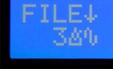
If the linked Song no longer exists because it was deleted from the module, a „?“ appears under FILE instead of a number.
Split Wave-Mode
Press the DATA controller and hold MORE to go into the split-wave mode.
Now, next to the FILE number the symbols for song and metronome appear. In split wave mode, the left and right signal of the song (WAV file) are automatically sent to separate channels in the SUB-mix (see also page 55) In effect, this means for situation 1 (see figure below) that the left channel of the song is treated as a "metronome" and the right channel as a "song". With Situation 2, it's the other way around.
Split wave Split-Wave Mode In Practice
You need the split-wave mode, e.g., if you want to play live with a backing track. To stay "on time", you maybe have produced a playback, with the music on the left and a matching click on the right. If you would let the song play just like that now, the click would be heard via the PA system. In the split-wave mode now, you have the option to route the side of the song that contains the click to a different channel in the SUB-mix and to set individually to which output the click signal is sent. In our example you would set up the routing in such a way, that the click is heard only on the headphones and not on the main output (OUT1·2). How this works in detail is explained from page 55 on.
9 UNIT Mode
In the mode UNIT you make general settings. On the pages in this section, you can change the general routing and trigger settings, adjust the internal mixer and calibrate the hihat. The settings made here are global and therefore apply to all KITS.
Changes in the mode UNIT are saved on the UNIT Main page (see SAVE on the next page).
9.1 UNIT – MIX
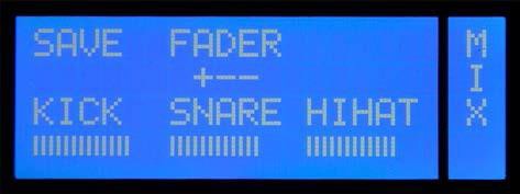
The DrumIt Three includes
a mixer that allows you to balance out the volume levels of the drum channels. There
are eight FADER groups whose
levels can be controlled
individually.
LINE (L controls the line-in channel's signal and ACMP (A) controls,
depending on the selection
within the kit, either the volume of the metronome
or of the song player.
The assignment of this group is fixed and can not
be changed.
The remaining
six groups are used to control
the volume levels of the drum channels.
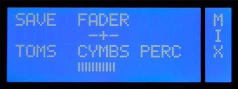
By default, the respective channels are already assigned to the following groups: KICK (K), SNARE (S), HIHAT (H), TOMS (T), CYMBS (C) and PERC (P). You can change the assignment of every channel individually on the INTF page (see page 52).
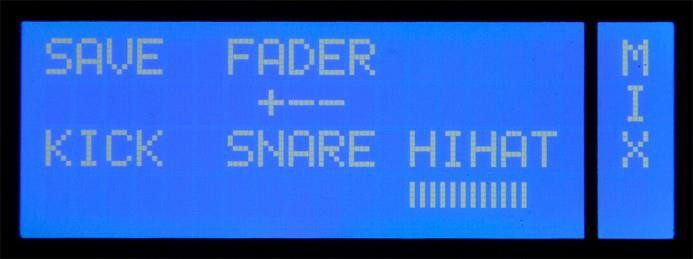
View
The mixer page shows the three currently
active FADERs - with full names. The "+" in the display „+ - -“ below FADER indicates
which FADER group is currently
selected. Again, you press the middle DATA button to switch to the next group of three: You will notice that the "+" moves accordingly. To the right of FADER
a horizontal bar meter is depicted, which indicates the
level of the output signal.
SAVE
If you have made changes in the UNIT mode, this will be indicated by a „?“ next to SAVE. To make these changes
permanent, press the left DATA button. The „?“ disappears and the changes
are saved. Please
be aware that for this the SAVE mode on the page PREF has to be switched
on (see page 59). Should the
"?" still be there after you pressed the DATA
button, the SAVE mode is disabled.
FADER
With the DATA buttons
above FADER, you select which FADER group is active, i.e. which FADERs can be changed
by the DATA controller. Press the knob to select the desired
mixer channel. The flashing entry refers to the internal mixer’s selected channel.
9.2 UNIT . CHAN
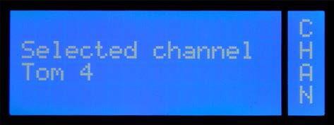
This page shows the currently selected trigger channel that can be edited. Channels can be selected in 2 ways: either strike the assigned pad or use the unit’s CHANNEL UP and CHANNEL DOWN buttons to navigate to the desired channel.
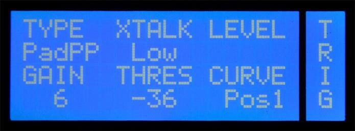
9.3 UNIT – TRIG*
On this page, you can change the trigger settings for the pads and optimize them for your playing style. The parameters on this page are particularly important if you want to hook up acoustic triggers or pads from other manufacturers to the DrumIt Three module.
TYPE
Here you can set what trigger type is connected to the corresponding drum channel.
TYPEs include various optimized trigger parameters for the respective pad type.
Please note that not all types are available on every trigger channel. See the table below for what options exist.
|
Type |
Brands (examples) |
Zones - configuration |
Information |
|||
|
Head/B ow |
Rim/ Edge |
Cross-stick/ Bell |
Choke |
|||
|
PadP |
2box, Roland |
Piezo |
Piezo |
- |
|
|
|
PaPSS |
Huaxin |
Piezo |
Switch |
Switch |
|
|
|
PaPSY |
Yamaha |
Piezo |
Switch |
Switch |
|
|
|
PadPS |
Roland, Alesis |
Piezo |
Switch |
- |
|
|
|
Rim |
various |
|
|
|
|
|
|
CyPSV |
2box |
Piezo |
Switch |
Velocity |
yes |
|
|
CyPSB |
Roland |
Piezo |
Switch |
Switch |
yes |
|
|
CyPS |
Alesis, Roland |
Piezo |
Switch |
- |
yes |
|
|
CyPSS |
Huaxin, Alesis |
Piezo |
Switch |
Switch |
yes |
|
|
CyPSY |
Yamaha |
Piezo |
Switch |
Switch |
yes |
|
|
HiHat |
various |
Piezo |
Switch |
- |
- |
control to Input B |
|
AcTr1 |
2box, Ddrum |
Piezo |
Piezo |
|
|
small drum |
|
AcTr2 |
2box, Ddrum |
Piezo |
Piezo |
|
|
medium drum |
|
AcTr3 |
2box, Ddrum |
Piezo |
Piezo |
|
|
big drum |
|
RubH1 |
2box |
Piezo |
Piezo |
|
|
Rubber Heads S |
|
RubH2 |
2box |
Piezo |
Piezo |
|
|
Rubber Heads M |
|
RubH3 |
2box |
Piezo |
Piezo |
|
|
Rubber Heads XL |
|
Kick1 |
various |
Piezo |
|
|
|
faster response |
|
Kick2 |
various |
Piezo |
|
|
|
slower response |
|
Type |
Instrument |
||||||||||||
|
|
Kick |
HH |
Snare |
Tom |
Rim |
Cymbal |
Acoustic |
various |
|||||
|
|
|
|
1 Zone |
2 Zones |
3 Zones |
1 Zone |
2 Zones |
|
1 Zone |
2 Zones |
3 Zones |
Trigger |
|
|
PadP |
|
|
x |
x |
|
x |
x |
|
|
|
|
|
x |
|
PaPSS |
|
|
|
|
x |
|
|
|
|
|
|
|
|
|
PaPSY |
|
|
|
|
x |
|
|
|
|
|
|
|
|
|
PadPS |
|
|
|
x |
|
|
x |
|
|
|
|
|
|
|
Rim |
|
|
|
|
|
|
|
x |
|
|
|
|
|
|
CyPSV |
|
|
|
|
|
|
|
|
|
|
x |
|
|
|
CyPSB |
|
|
|
|
|
|
|
|
|
|
x |
|
|
|
CyPS |
|
|
|
|
|
|
|
|
x |
x |
|
|
|
|
CyPSS |
|
|
|
|
|
|
|
|
|
|
x |
|
|
|
CyPSY |
|
|
|
|
|
|
|
|
|
|
x |
|
|
|
HiHat |
|
x |
|
|
|
|
|
|
|
|
|
|
|
|
AcTr1 |
|
|
|
|
|
|
|
|
|
|
|
x |
|
|
AcTr2 |
|
|
|
|
|
|
|
|
|
|
|
x |
|
|
AcTr3 |
|
|
|
|
|
|
|
|
|
|
|
x |
|
|
RubH1 |
|
|
|
|
|
|
|
|
|
|
|
|
x |
|
RubH2 |
|
|
|
|
|
|
|
|
|
|
|
|
x |
|
RubH3 |
|
|
|
|
|
|
|
|
|
|
|
|
x |
|
Kick1 |
x |
|
|
|
|
|
|
|
|
|
|
|
|
|
Kick2 |
x |
|
|
|
|
|
|
|
|
|
|
|
|
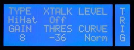
XTALK
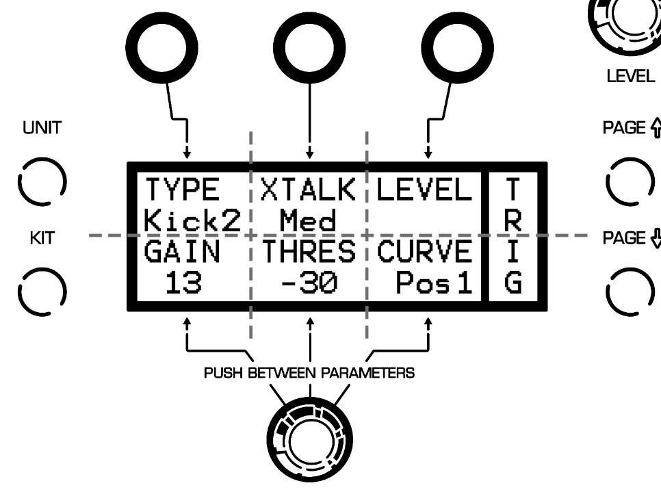
This feature can be used to prevent unwanted trigger impulses (cross talk) from other pads. If, e.g. a hard cymbal stroke triggers a tom sound, you can suppress the latter. Just select the channel of the unwanted sound (in our case: tom) and change the value of XTALK. You have the following parameter values: Off (no suppression), Low (low suppression), Med (medium suppression), High (maximum suppression).
LEVEL
Here you can read the level of the trigger signal. There are three different views
you can select by pressing
the DATA
button to the right.
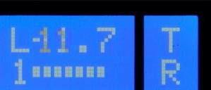
View 1 The number indicates which zone was triggered last. The graph displays the signal level. While triggering, the dB value of the signal is shown in the top row.
View 2 This view shows the last four strokes. You see the signal level in the first row and the zone number in the second row.
View 3 This view gives you information about the triggered MIDI note number (N) and the velocity value (L).
GAIN
With GAIN, you can increase the level of the trigger signal. This feature is important if you use acoustic triggers or pads from other manufacturers, which may have comparatively lower trigger output. In addition, you can customize the triggering behavior to your personal playing style.
Set GAIN so that exactly all LED-meter segments are lit when you hit the hardest (see above). You have an adjustment range from +1 to +24 dB. With a GAIN value higher +12 dB the THRES value is automatically set to -36 to avoid double triggers.
The drum channels CYMB1-3 have an additional GAIN parameter for the bell signal.
First, set the GAIN value (number) for the zone “bow” so that the hardest stroke triggers no bell sound. Then you can press the DATA knob while holding the MORE button to adjust the GAIN value for the zone “cup”.
You can switch between L ((low - minimum GAIN increase), M (medium increase) and
H (high increase).
THRES
With the threshold value you determine how strong the lightest stroke has to be for triggering an impulse. Useful you when you need pad to be less sensitive for stray triggers. You have a control range from –48 to –18dB.
Low Threshold
The lower you set this value, the higher is the risk of double-trigger impulses and crosstalk.
CURVE
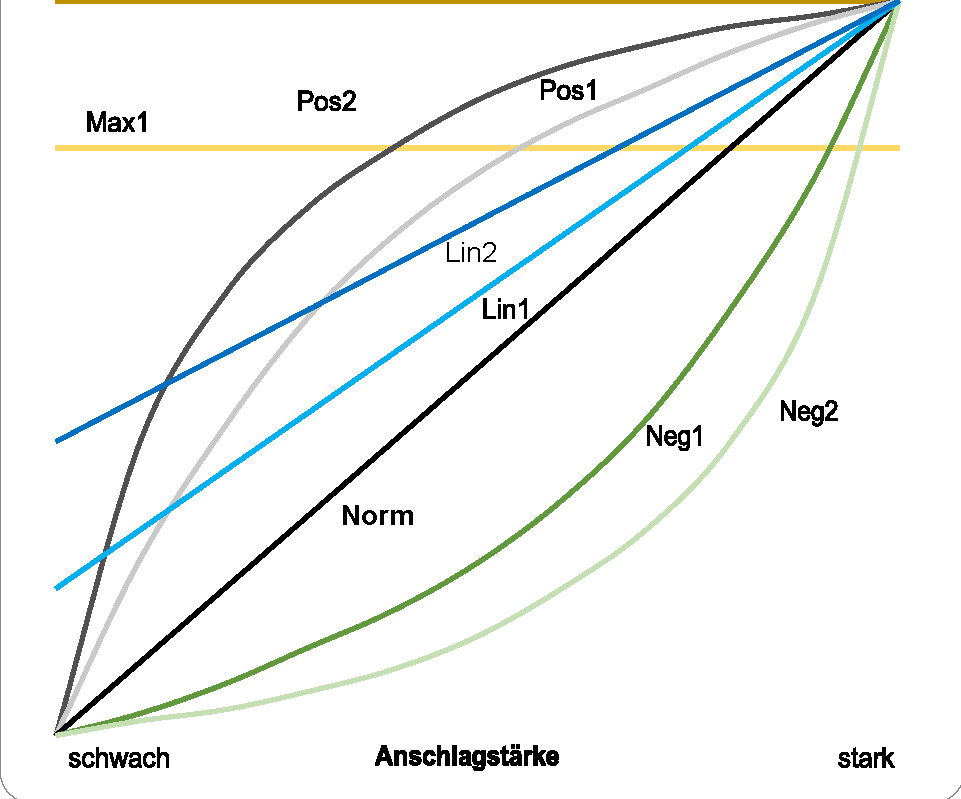
With CURVE you can set the relationship between velocity and signal volume. Nine different curves are available. Depending on the sound or application situation, different settings can make sense.
Take advantage of this feature also to adjust the trigger behavior to your playing.
Max2: Regardless of the velocity, a fixed signal level
of 0dB is generated.
Max1: Like Max 2, although
with a fixed signal level
of -6 dB.
Pos2: The signal level increases more than the velocity.
But at high velocities, the signal level increase is much smaller, i.e. the signal
level changes only marginally with
real hard strokes.
Pos1: Like Pos2 but the difference
is
not as pronounced.
Lin2: The faintest
stroke triggers already a high signal level. With increasing velocity, the signal level
then grows steadily and
evenly.
Lin1: Like Lin2, but the initial
volume level is lower.
Norm: The signal
and velocity levels increase
at the same rate (linearly).
Neg1: The signal
level grows with increasing
velocity, at first only slowly. Only at higher stroke strengths the
signal level increases
accordingly.
Neg2: Like Neg1, although the difference is more pronounced.
Adjusting Trigger Behavior with CURVES
With CURVES you can optimize the trigger behavior so it suits your playing best. It pays to experiment a little with the parameter values.
Depending on your playing style, the various options can give
you a more realistic feel.
CAL
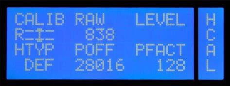
On this page important adjustments for the hi-hat are made.
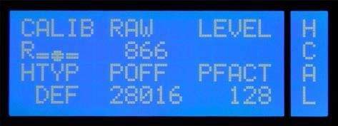
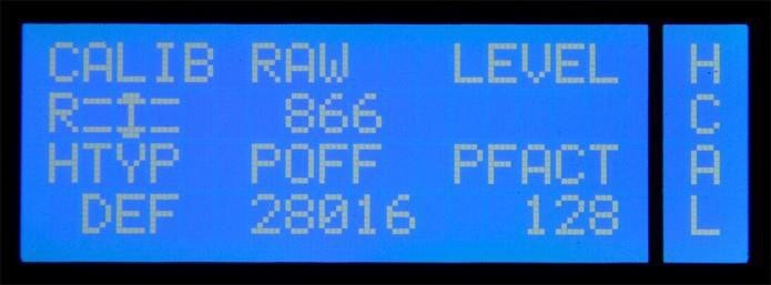
CALIB
On this menu page you can calibrate the hihat, i.e. adjust it to your playing. Because of the importance, we have dedicated an extra chapter to this subject. Please read the detailed explanations starting on page 19.
RAW
Depending on the hi-hat pad you connect, you may have to change the RAW setting to ensure optimum performance. The RAW value can be set with the small recessed screw (HH Cal) on the module’s back panel. The values below are merely indications of what might work for you. Feel free to tweak the setting to adapt the response to your playing style.
Yamaha: 850-900
Roland: 800-850
Alesis: 830-880
2BOX: 600-650
LEVEL
Here you can read the signal level of Zone 9 (pedaled hihat - the DATA button has no function).
HTYP With this parameter you specify the hi-hat type you have connected.
DEF All popular hi-hat types and brands
2BOXHH 2BOX DrumIt Five Hi-hat
ALEHH Alesis Crimson hi-hat controller
POFF
This parameter allows you to change the hi-hat’s calibration range: higher values extend the range, while lower values narrow it down. Bear in mind that changing this setting also affects the PFACT setting. We recommend editing this parameter only once you are thoroughly familiar with the system.
PFACT
Increase this value to raise the calibration threshold. This is useful for a consistent “foot chick” (pedaled hi-hat) and “foot splash” (quick release of the pedal after a chick) sound. We recommend taking your time to find the setting that you are most comfortable with.
9.5 UNIT – HSET
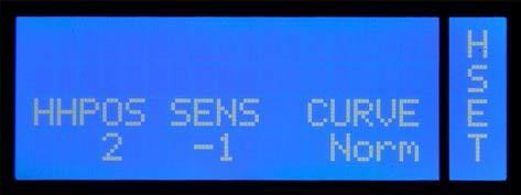
HHPOS
This parameter allows you to set the hi-hat’s aperture. This setting applies to all KITs (presets). When this value is changed, the HH Controller loses its function—again globally.
This function may come in handy if you don’t want to use a hi-hat controller and prefer a fixed aperture setting instead.
The setting range is 1 (hi-hat completely open) through 31 (hi-hat completely closed). “Off” means that the hi-hat controller can be used.
SENS
Set the sensitivity of the hihat pedal (pedaled signal) here. You have a control range of - 6 to +6 dB.
CURVE
There are nine different trigger curves. Select the value that supports your playing best by rotating the DATA controller. Detailed information on the topic CURVE can be found in the notes to page TRIG on page 46 ff.
9.6 UNIT – SPEC
Use this page to fine-tune the trigger settings (UNIT-TRIG).
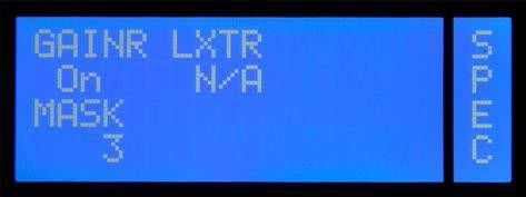
GAINR
“GAINR” (gain reduction) allows you to decrease the selected channel’s sensitivity. This function may come in handy for pads that deliver a powerful signal. Together with the “GAIN” parameter on the “UNIT-TRIG” page, this allows you to specify the optimum input sensitivity.
Please bear in mind that this function is only available for the hi-hat and cymbal 1~3 channels.
LXTR
This parameter allows you to eliminate or minimize crosstalk between the head and the rim channels (local xtalk reduction). High values mean that crosstalk is attenuated more radically.
The following parameters are available: Off, Low, Med, High, vHigh
MASK
Mask Time is used to avoid double triggers. This sets the duration during which the module will ignore subsequent trigger signals. This is useful for avoiding that head vibrations generate spurious trigger signals. You will probably need this parameter when using acoustic drum triggers.
MASK
Start by trying out extreme MASK settings to get to grips with how this function works.
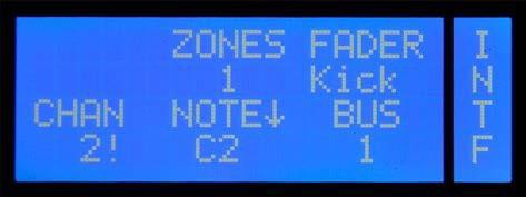
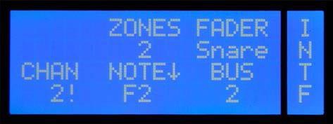
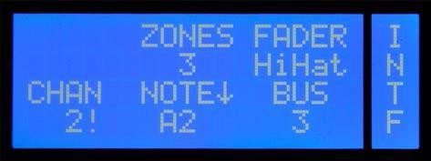
9.7 UNIT – INTF*
On this page you make the global routing and MIDI settings for each trigger channel. Here you set to which BUS the respective signals should be sent and the settings for the MIDI control of each channel. Application examples expanding on this topic can be found from page 63 on.
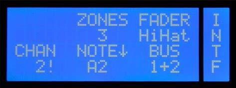
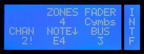
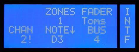
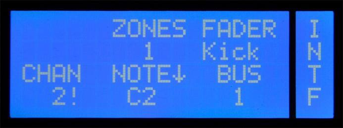
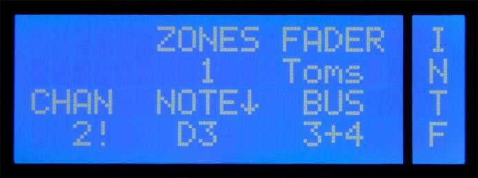
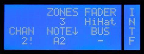
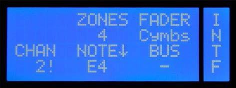
ZONES
Here you can see how many (sound) zones are assigned to a trigger channel. The number of zones indicates how many MIDI notes are used for the channel. Please note that for all trigger channels with multiple zones the MIDI notes are a consecutive sequence that can be shifted, but not separated from each other.
example:
Cymbal 2 has 4 zones and has B4 assigned as MIDI note. Therefore, the MIDI note sequence for the cymbal 2 is:
B4 = bell, C5 = bow, C#5 = edge, D5 = choke function.
FADER
Select here to which FADER group of the internal mixer (see also mode UNIT Page MIX on page 41 the respective trigger channel should be assigned. Please note that for this purpose only the first six FADER groups are eligible, the assignment of the groups LINE, ACMP is fixed.
CHAN
This sets the MIDI channel
for the transmitting or receiving of MIDI signals for the respective drum channel. You can assign a different
MIDI channel (1 to 16) to each drum channel.
The default setting for all channels is the global MIDI channel (see also menu item MIDI on page 58). This channel is marked
with " " and can be set manually. To do this, turn the DATA controller to the far
right.
NOTE¯
Here you can specify with which MIDI note the respective channel will send and receive "NOTE ON" and "NOTE OFF" messages with. Channels with multiple zones use a consecutive sequence of MIDI notes (see also ZONES, as well as explanations about MIDI notes on page 12). Push the DATA controller while holding the MORE button to toggle between the display of the note (e.g. "C1") and the display of the respective MIDI note number (e.g. "24").
The MIDI note number "0" equals the MIDI note "C-1“. You can use the range from 0 (C- 1) to 127 (G9).
Default MIDI Configuration (see also page 12)
Explanations to the figure:
P1 to P5 = PERC channels (see also explanations on PERC channels on page 13) o = choke function (G4, D5 and G5)
MIDI Messages Hi-Hat and Cymbals
A cymbal stroke at the zones 1 (Bell), 4 (Bow) or 8 (Edge) generates a NOTE ON and a NOTE OFF command. A choke generates a NOTE ON command which continues until the pad is released (NOTE OFF).
Playing the hi-hat
in the zones 4 or 8 also generates
both a NOTE ON and NOTE OFF signal.
Parallel to this, the DrumIt Three module produces pedal controller data. When you step on the hi-hat pedal (Zone 9), initially
only a NOTE ON message is generated. When the pedal moves back up, a NOTE OFF
message is transmitted. The time
between the NOTE ON
and NOTE OFF message determines whether a chick (long duration)
or a foot splash sound (short
duration) is generated.
BUS
Here you can send signals to BUS channels according to your needs. There are four single BUS channels (1-4) and two BUS groups (1+2, 3+4).
BUS
Think of a bus as an internal signal path. It leads the respective signal to a specific output (direct out).
Which BUS signals can be routed to which output jacks is shown in the following table:
|
|
OUT1 |
OUT2 |
OUT3 |
OUT4 |
PHONES |
|
BUS1 |
○ |
|
|
|
○ |
|
BUS2 |
|
○ |
|
|
○ |
|
BUS3 |
|
|
● |
|
○ |
|
BUS4 |
|
|
|
● |
○ |
● = fixed ○ = optional
9.8 UNIT – OUT
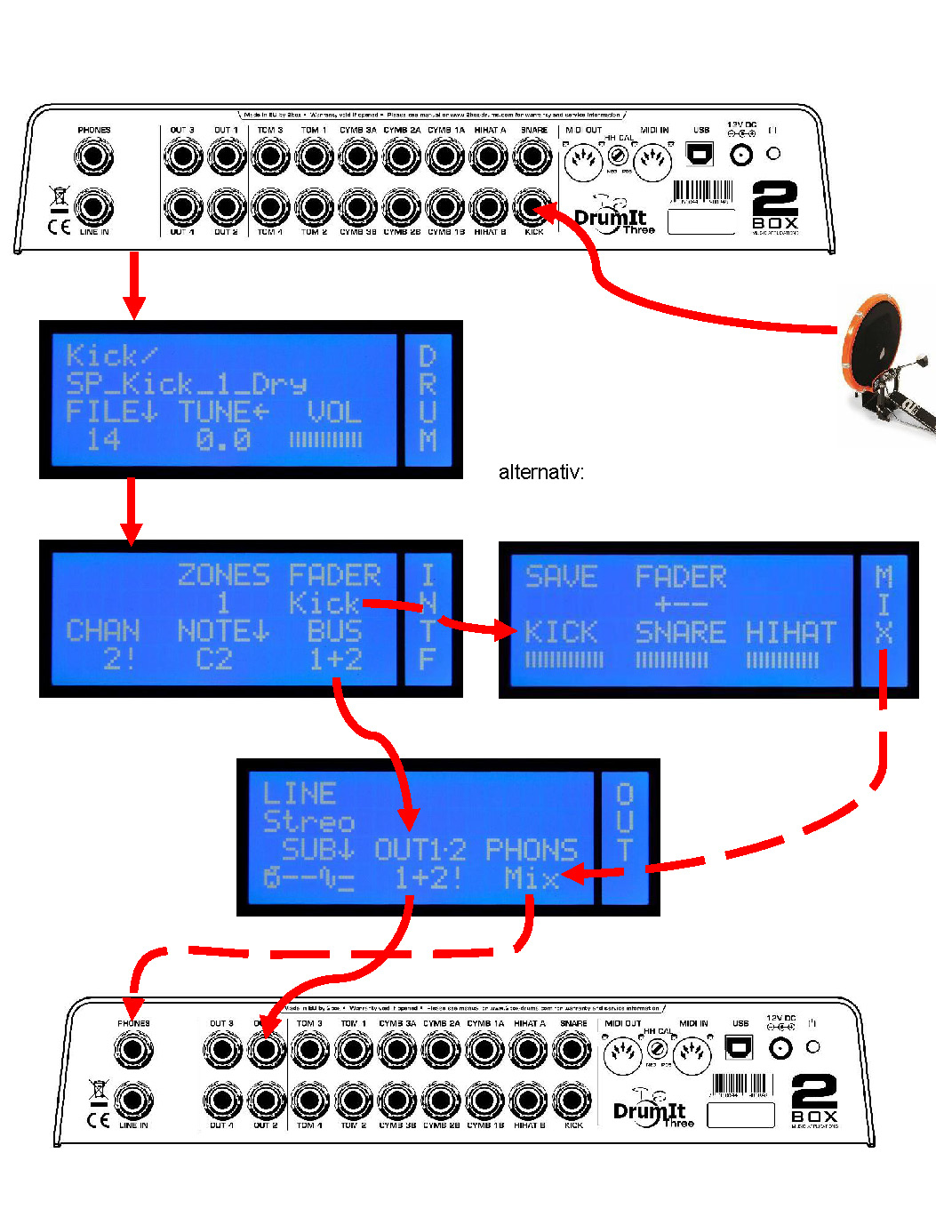
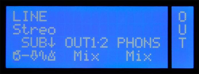
Concerning the signal routing the DrumIt Three module offers a number of options. In Chapter 10. “Signal Flow and Routing Options” on page 63 some connection scenarios are listed, which will explain clearly what routings are available.
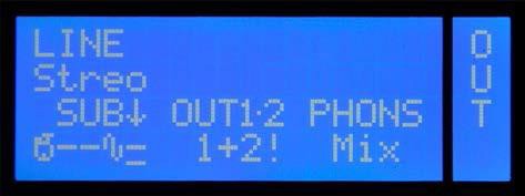
LINE
This parameter is important if you want to connect a mono signal to the line-in jack. Select "Mono" so that the fed-in signal is heard in the center of the stereo sound image (only the signal of the tip of the jack will be transmitted). If "Stereo" is set (logically the default setting for stereo sources) an incoming mono signal will be placed only on the left channel.
Line In - Mono
This setting is useful if you are using the DrumIt Three module as an in-ear monitor station and only a single monitor signal is provided by an external mixer (AUX). In this situation, you should select "mono" so that the signal will sound in the middle, i.e. on both sides of the headphones.
OUT1·2
This determines which signal is going to the main output jacks (OUT1·2). You can choose from the following options:
Mix
The entire sum signal of the internal mixer (see also page 41) (all instruments, metronome, line in and the song player).
Mix
Like "Mix", only with a fixed volume. The output volume no longer depends on the LEVEL control. The control can thus be used exclusively for the headphone output.
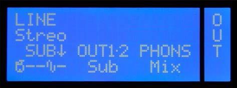
Sub
In this setting, the sub-mix signal is used (see SUB).
Sub
Like "Sub", only with a fixed volume - independent of the LEVEL control.
1+2The Signals of BUS 1 and BUS 2 are outputted with a fixed volume on the jacks OUT1 and OUT2, which then serve as additional individual outputs (Direct out).
Fixed Volume - -
Decoupling the output volume from the LEVEL control makes especially sense in live use because this ensures that the volume of the drum signal on the PA system is not changed when you change the volume of the headphones.
SUB¯
As an alternative to the complete signal from the internal mixer, you can create a so- called "SUB-mix." The SUB-Mix allows you to disable certain channel groups of the mixer, so that they don't go, for example, to the main output. The following groups of signals are available:
Drum channels (kick, snare, toms, cymbals, hi-hat, perc)
line in signal
song
signal
metronome
Select a group by rotating the DATA controller and disable or enable the signal for the sub-mix by pressing
the controller while
holding the MORE button.
Song and Metronome
The signals "song" ( ) and "metronome" ( ) are treated separately in the sub-mix, although they share one FADER in the internal mixer (ACMP). The reason for this is that per kit only either a song or the metronome can be selected. A differentiation is not necessary in the mixer. But through settings in the sub-mix it can be ensured that the metronome signal, independent from the chosen kit, is generally sent only to the headphones (PHONS).
PHONS
Allows you to specify which signal will go to the headphone output. As with „OUT1·2“
you can choose between the options
mix and sub. . In addition,
various BUS groups can be
selected: BUS1+2, BUS3+4.
9.9 UNIT – METR
On this page you can change the sound settings of the metronome. Please note that these are global settings that affect all KITs.
FILE¯
Like on the DRUM Page in the KIT menu, you can select a sound by rotating the DATA controller. Pressing the DATA controller and holding the MORE button switches to FOLD and you can navigate through the folder structure. The first line of the display shows the folder, the second line, as usual, the name of the sound.
TUNEß
TUNE changes the pitch of the sound. The lowest pitch is at -12. The highest achievable pitch is dependent on the selected sound. Four half-steps up (+4) are common. But there are sounds that can be changed even more or less than 4 half steps up. If you press the controller while you hold the MORE button, you switch into a fine-tuning mode and you can adjust the pitch in decimals.
DECAY
This value determines how long the underlying sample of the sound will be played back. With the setting ∞ (infinity), the whole sample will be played back. Turn the controller to the left to shorten the sound. In practice, it is recommendable to shorten the sound length using DECAY in order to generate a clearly audible and precise click.
With the DATA buttons you
can listen to the various
zones of the selected
sounds. Please note that
only the first
zone (left DATA button) can be used
as
a metronome sound.
9.10 UNIT – MIDI
On this page, you can change the global MIDI settings.
PRCHG
You can choose between on and off. If you have selected "On", the DrumIt Three module can both send and receive MIDI program change messages. This is useful. e.g. changing KITs via a MIDI keyboard or, in the reverse case, to control an external MIDI device from the DrumIt-Three-module.
LOCAL
Turn LOCAL "Off" to disable the internal sound engine. Now the DrumIt Three only transmits MIDI messages and no longer triggers the internal sounds. This setting is useful if you want to control an external sound source without having the DrumIt Three sound engine always playing along.
THRU
When you switch from "Off" to "On" here, MIDI-IN- signals are routed directly to the MIDI- OUT This way, an external MIDI device can control both the DrumIt-Three-module and another MIDI device connected to the DrumIt Three.
CHAN
Here you can specify on which MIDI channel program changes and MIDI note messages for the various trigger channels will be sent and received. Please note that the global MIDI channel (Program Change) setting made here can be set to an individually trigger channel (see also menu UNIT-INF explained on page 52).
PED
Set here the controller format for the foot controller of the hihat. You can choose between CC1 (modulation wheel) and CC4 (pedal control). For each controller format there are 4 different modes.
▼: value 0 for the open and value 127 for the closed hihat
▼!: In difference to ▼ the controller data is sent continuously and not just once with the
NOTE-ON command.
▲: value 0 with closed and value 127 with open hihat
▲!: In comparison to ▲ the controller data is sent continuously and not just once with
the NOTE-ON command.
9.11 UNIT – PREF
SAVE
This parameter determines whether changes in the modes KIT and UNIT can be saved or not. Select "On", to be able to save your results permanently after successful programming by pressing the left DATA button. The saving process is executed on the main page of the modes (KIT Page PROG or UNIT Page MIX). As soon as something is changed in the original settings, this is indicated by a„?“ displayed to the right of SAVE.
In the off mode, your changes will not be saved.
SAVE-Off-Modus
SAVE-off mode is particularly useful when several percussionists play on your DrumIt Three (e.g. at a festival) and you want to prevent
people from tampering with your drum kits and
configurations and then
saving that.
TRIG
Here you can set the volume at which the sounds will be played back when pressing the TRIG button - i.e. when prelistening. The available range extends from -48 to 0 dB (default -6 dB). You can turn off the prelisten function of the TRIG button as well. Just select "off".
INIT¯
THis function resets the DrumIt-Three-Module to factory default. Rotate the DATA controller to select the part you want to reset. After selecting the desired value, press the DATA controller ↓ while you hold the MORE button.
There are various options available.
Unit resets all settings of the mode UNIT
Kit1 bis 100 only resets the settings of the selected KIT
KtPrg resets the order of the KITs to factory default
All resets all KITs and the order of the KITs to factory default
If you have completed the process successfully, Done appears on the display. If NoChg
appears, the system has not
made any changes.
Module Reset
To restore the factory default settings of your module, you can use the function INIT (see above). You can also download a new DrumIt.dkit bank file from our website and overwrite the existing file on your module with it. Please note that a complete init or loading a new DrumIt.dkt files also corresponds to factory default sounds. If you have deleted sounds a “?” will appear under FILE for that channel in the Kit.
Sounds can be downloaded for www.2box .se/downloads.
Personal Factory setting
The factory default settings are saved in the file „DrumItInit.dkit“ (see explanations on page 10). With a trick it is possible to create a personal init file, so you have access to your own settings instead of the default settings in case of emergency. For this, back up the original DrumItInit.dkit file on your computer (for the worst-case scenario) and copy your personal "DrumIt.dkit" file to the module. Rename this copy to "DrumItInit.dkit".
This way you create an initialization file that contains your personal settings.
9.12 UNIT – MEM
On this page
you can read
information about memory usage (DATA
buttons and DATA controllers have no function).
FLASH Displays the size of the internal
flash memory.
USED Percentage of the flash memory that is used.
FREE Percentage of the flash memory that is still free and available to you for additional sound files.
Memory Capacity
When you frequently copy additional sounds to your DrumIt Three-module, it may occur that there is not enough memory available. In this case, you should clear up your module to make room for new sounds. Make a back-up of the entire contents of your module and in the second step, delete those sounds from the module, you don’t like. This way, you create free space and still have all the original 2BOX sounds archived.
9.13 UNIT – INFO
This page gives you information about the software version of your module (DATA buttons and DATA controllers have no function).
SERNR Serial number of your module
BOOT software version of the boot program
OS software version
of
the operating system
1
The pads are connected to the corresponding drum channel input (in our example, a kick-pad).
2
In the mode KIT on the page DRUM a sound is assigned to the trigger signal of the respective drum channel, and the overall volume of the signal is set. Alternatively, the volume can be set on the page VOL, since both VOL controls are identical (see page 33).
3
The signal of the drum channel is then routed on the page INTF in the mode UNIT. The signal is sent to both the selected BUS (BUS 1 here) and to the fader group of the internal mixer (here KICK / K). The volume level of the signal set on the page DRUM (resp. VOL) remains unaffected from this (see ). Now the signal is present in two different places. Once on the BUS (solid line) and once in the internal mixer (dashed line).
4
The two parallel signals can then be assigned to the desired outputs in the mode UNIT on the page OUT (BUS and mixer). In this case, BUS 1 is assigned to the outputs OUT1·2 and the mixer signal to the headphone output (see ).
Result:
This way the volume of the kick drum can be changed for the headphones without affecting the direct out signal. For this, you only need to adjust the fader "kick" in the mixer accordingly. The mixer does not affect the BUS signal at the output OUT1, since these are two independent signal paths.
The examples on the following pages show what options you have with the routing capabilities of the DrumIt Three. Of course, these are just a few configurations and not an exhaustive list of all the options that are available for your personal use.
Please note that there is not an example for every drum channel in the following explanations. Only the essential pages are shown, comments on the corresponding pages are noted below.
Situation 1 - Rehearsal Room: The same signal on PA and headphones
You connect the DrumIt Three module to a small PA in the rehearsal room and/or play with headphones.
All signals from the mixer (MIX) (drum channels , line-in signal , song player and metronome ) are on both the headphones and the output jacks (OUT1·2). The bus settings on page INTF do not affect the result. The volumes of the various instruments are controlled with the mixer on the page MIX.
| KICK | SNARE | HIHAT | TOMS | CYMB | PERC | LINE | SONG | METR | |
| Output | |||||||||
| OUT1 | x | x | x | x | x | x | x | x | x |
| OUT2 | x | x | x | x | x | x | x | x | x |
| PHONES | x | x | x | x | x | x | x | x | x |
For both OUT1·2 and PHONS the setting is Mix.
Situation 2 – Live 1: Mix for the PA, click and monitor signal on the headphones
In this setup, you want to output the drum signals and songs as a stereo mix. At the same time you want to use the DrumIt Three as "in-ear monitor station" (stereo mix, metronome, external monitor signal).
For this, you connect the output jacks OUT1·2 of the DrumIt Three with an external mixer and simultaneously the monitor output of the mixer (Aux) with the line-in jack of the DrumIt Three module.
On the headphone output are now the signals of the DrumIt Three (drum channels, metronome, song player) plus the external monitor signal (e.g. vocals, bass, guitar).
For the stereo output, use the SUB mix. So that neither the signal of the metronome nor of the line-in channel are in the stereo sum, the respective sub-groups are switched off (see also page 55).
| KICK | SNARE | HIHAT | TOMS | CYMB | PERC | LINE | SONG | METR | |
| Output | |||||||||
| OUT1 | x | x | x | x | x | x | x | ||
| OUT2 | x | x | x | x | x | x | x | ||
| Phones | x | x | x | x | x | x | x | x | x |
The output jacks OUT1·2 get only the SUB-mix (with no line-in and metronome). The headphone jack is fed with the complete mix (internal mixer).
Situation 3 – Live 2: A maximum number of individual signals for the PA, click and monitor signal only in the headphones
In this scenario, the goal is to transmit a maximum number of individual drum signals to allow the sound engineer to prepare a convincing mix. Here, the DrumIt Three is used as “in-ear monitor station” (stereo master bus, metronome, external monitor signal).
Connect the DrumIt Three’s OUT1~OUT4 sockets to the external mixing console and the console’s monitor output (AUX) to the DrumIt Three’s LINE IN socket.
The DrumIt Three’s PHONES socket transmits the drum channel, metronome and song player signals, plus the external monitor signal (e.g. vocals, bass, guitar).
Outputs 1~4 transmit drum signals. OUT1 and OUT2 are used as direct outputs in this scenario. The internal signals (LINE, SONG, METR) are therefore only transmitted to the PHONES socket. The hi-hat and the cymbals share one output, as do all toms and the additional percussion channels.
| KICK | SNARE | HIHAT | TOMS | CYMB | PERC | LINE | SONG | METR | |
| output | |||||||||
| OUT1 | x | ||||||||
| OUT2 | x | ||||||||
| OUT3 | x | x | |||||||
| OUT4 | x | x | |||||||
| Phones | x | x | x | x | x | x | x | x | x |
Busses 1 and 2 are assigned to OUT1 & 2
The kick drum is assigned to BUS 1
The snare is assigned to BUS 2
The hi-hat is assigned to BUS 3
The cymbals are also assigned to BUS 3
The toms are assigned to BUS 4
Situation 4 - Studio: The most important Instruments Separately
You connect the DrumIt Three to an external mixer and want to provide the sound engineer with as many separate channels as possible.
In this example, the PHONES socket is used
as
additional output (5+6). The internal song player and
the
metronome are not needed in this scenario. This allows us to have the cymbals and hi-hat share one stereo output pair and to use a second pair for the toms and percussion sounds. The advantage
of this approach
is
that the aforesaid signals can be panned across the stereo field.
| KICK | SNARE | HIHAT | TOMS | CYMB | PERC | LINE | SONG | METR | |
| Output | |||||||||
| OUT1 | x | ||||||||
| OUT2 | x | ||||||||
| OUT3 | x | x | |||||||
| OUT4 | x | x | |||||||
| PHONES L | x | x | |||||||
| PHONES R | x | x |
Kick: only BUS 1 is selected
Snare: only BUS 2 is selected
Toms: stereo on BUS 3+4
Hihat: no BUS assigned
Cymbals: no BUS assigned
Be sure to set all channels—except HIHAT and CYMBS—to the minimum level on the internal mixer (“UNIT-MIX” page).
Be sure to set all channels—except HIHAT and CYMBS—to the minimum level on the internal mixer (“UNIT-MIX” page).
Just try it
11 Technical Data
Connectors:
10 x Trigger Input (6.3mm stereo jack)
4 x Control-Input for Hihat and Cymbals
(6.3mm stereo jack)
1 x Line In, stereo (6.3 mm stereo jack)
4 x line out, mono (6.3 mm mono jack)
1 x headphone
jack (6.3 mm stereo
jack)
1 x USB 1.1 (Full Speed)
1 x MIDI IN
1 x MIDI OUT
1 x power supply (12 V DC, external power supply)
Display / Memory Type:
LCD (20 x 4 characters)
4 GB Flash memory
Controls:
11
x pushbutton
1 x rotary push controller
(endless)
1 x rotary controller
Amount of manageable Data
The operating system can manage up to 8,000 dsnd files, 1,000 folders and 800 Wav files.
Name Size
File names can have up to 63 characters and folder names (including subfolders) up to 127 characters.
11 Update
Thanks to the Open Sound System of 2BOX the module can be updated easily and comfortably using drag and drop.
This way you can keep your DrumIt Three always up to date and benefit from the operating system updates, new features and technical enhancements.
1. Download the current operating system from our website (www.2box-drums.com). The file format of the operating system is a .bin file (see picture).
2. Start the module in USB mode (see page 9).
3. Copy the new .bin file to the module with drag & drop.
4. Restart the module. The module shows the new operating system number during the boot process at the bottom right (you can also get this information in the mode UNIT on the Page INFO).
5. Done
You don’t need to delete the old operating system file. The module
will
automatically recognize the
newer version. In the example
below, the system
recognizes the file DrumIt120.bin (OS 1.20) as the latest
version and ignores
the file DrumIt110.bin (OS 1.10).
Choosing Between Operating Systems
During the boot process, you have the option to choose between the various operating systems that are available on your module. To do so, press the middle DATA button while powering up.
Please note:
Settings in the modes KIT
and UNIT that relate to functions
of a higher operating
system will be
lost if you
edit and save the same part (e.g. a kit) in an
earlier version of the
operating system.
After you have selected the desired operating
system with Prev/Next (left and middle DATA button),
start the boot process by pressing
the DATA
button to the right (load).
12 FAQs
How can I adjust the volumes of the instruments to each other?
For this purpose you have an internal mixer in the mode UNIT on the page MIX (see page 41). Refer also to the detailed explanations on this topic starting on page 63.
How can I save my settings?
Changes can be saved in both modes UNIT and KIT at the main page (KIT PROG respectively UNIT MIX) by pressing the left DATA button. Any changes you made in the respective areas are indicated by a "?". Refer also to page 21 and page 41. In order to be able to save, you have to have the SAVE function enabled on the page PREF in the mode UNIT (see page 59).
How can I optimize the response behavior of the hihat to my needs?
Special configuration options for the hi-hat can be found in the mode UNIT on the pages HPED (see page
49) and TRIG (see page 43). In any case, you should calibrate the hihat properly. It is also recommended that you experiment with the trigger-curves and GAIN. Please note that an electronic hi-hat always responds somewhat different from a normal hi-hat.
How can I assign a different sound to the Rim?
Call up the page DRUM in the mode KIT and select the desired PERC channel by simultaneously pressing the MORE button and the respective Drum Channel button. Now you can assign a sound to the PERC channel as accustomed (see also page 29).
How can I avoid double triggers?
At first, you should check the tension of the heads of the affected pads. It should be even and not too loose. You should also make sure that the pad is mounted properly and does not vibrate too much. If you still have problems with double triggers, you can change the trigger settings (GAIN and THRES) on the Page TRIG in the mode UNIT. See section 10.2 UNIT – TRIG* starting on page 43.
How do I assign individual drum channels to direct outputs?
The DrumIt Three provides many routing options. Read from page 63 on, what settings you need to make in order to assign individual channels directly to specific outputs.
Can I connect two pads to one plug and assign different sounds?
Absolutely. The drum channels TOM 1 to TOM 4 and SNARE have a parallel PERC channel, which can be utilized separately using a Y-split cable. How this works is described in detail on page 13 and page 15.
Can I assign a separate MIDI channel to each drum channel?
Yes, in the mode UNIT on page INTF. How this exactly works is described on page 52.
I've lost a cable. Do I need to buy something special?
The 2BOX cables are standard stereo jack cables (6.3 mm).
Can I use the DrumIt Three with acoustic triggers?
Of course. The DrumIt Three works fine with the products of the major manufacturers, the most common triggers have been tested successfully with the DrumIt Three. In the UNIT mode on page TRIG you will find specific trigger TYPES (AcTr1, AcTr2 and AcTr3) and other parameters (GAIN, THRES), that allow you to set the module so it is perfectly suited to the use with acoustic triggers. Please refer to the section
10.2 UNIT –
TRIG* starting
on page 43.
Compatibility List–DrumIt Three & Five
The following list is not exhaustive, because testing all current and legacy pads on the market would
be rather time-consuming. We do promise, however, to keep this list up-to-date whenever we are able to confirm the compatibility of products we haven’t tested so far. If you don’t see the type or manufacturer of (one of) your pads, please do not conclude that your pad(s) won’t work with the DrumIt Three. Rather, compare the technical specifications of your pads with the requirements listed in the table below. If the specs match the listed requirements, your pads may work even though they do not appear in the list of compatible products.
If in doubt, just ask your dealer or send an e-mail to: drumit3-compatibility@2box-drums.com
|
Pad Type |
Kick |
Snare/Tom |
Hi-hat pad |
Hi-hat controller |
|
Specifications |
Piezo (head) |
Piezo (head) |
Piezo (bow)/Switch (edge) |
Adjustable resistor, active hall generator or switch |
|
|
|
Piezo (head)/Piezo (rim) |
Piezo (bow) |
|
|
|
|
Piezo (head)/Switch (rim) |
|
|
|
|
|
Piezo (head)/Switch (rim)/Switch (cross-stick) |
|
|
|
Products |
2box |
2box |
2box |
|
|
|
Alesis Crimson series |
Alesis Crimson series |
Alesis Crimson series |
|
|
|
Alesis DM 10 series |
Alesis DM 10 series |
Alesis DM 10 series |
|
|
|
Alesis Strike series |
Millenium MPS series |
Alesis Pro X |
|
|
|
Roland KD120 |
Roland PD-100 |
Millenium |
|
|
|
Roland KD140 |
Roland PD-125 |
Roland FD-7 |
|
|
|
Roland KD7 |
Roland PD-8 |
Roland VH-10 * Note 1 |
|
|
|
Roland KT-10 |
Roland PD-85 |
Roland VH-11 * Note 1 |
|
|
|
Yamaha KP-65 |
Roland PDX-100 |
Roland VH-12 * Note 2 |
|
|
|
Yamaha KP100 |
Roland PDX-8 |
Roland VH-13 * Note 2 |
|
|
|
|
Roland PDX-6 |
Yamaha RHH135 |
|
|
|
|
Yamaha XP-80, XP100SD, XP120T, XP120SD (3 Zone) |
Yamaha HH-65 |
|
|
|
|
|
ATV aD-H14* Note 3 |
|
|
|
|
|
Go Edrum GH6 * Note 1 |
|
|
Pad Type |
Cymbals |
Trigger |
Miscellaneous |
|
Specifications |
Piezo (bow) |
Piezo (head) |
Piezo |
|
|
Piezo (bow)/Switch (edge) |
Piezo (head)/Piezo (rim) |
|
|
|
Piezo (bow)/Switch (edge)/Bell (switch) |
|
|
|
Products |
2box |
2box TrigIt* Note 5 |
DDrum Trigger Tube |
|
|
Alesis Crimson series |
DDrum Chrome Elite |
Roland BT-1 |
|
|
Alesis DM 10 series |
DDrum Pro |
Pintech Dingbat |
|
|
Alesis Strike 16” 3 zone |
DDrum Red Shot |
|
|
|
Millenium MPS series |
ddt AT series |
|
|
|
Roland CY-12C & CY-12C/R * Note 4 |
ddt Truss series |
|
|
|
Roland CY-13R* Note 4 |
Roland RT10 series |
|
|
|
Roland CY-14C |
TDrum Black Shot series |
|
|
|
Roland CY-15R* Note 4 |
TDrum Pro series |
|
|
|
Roland CY-8 |
Yamaha DT50 series |
|
|
|
|
|
|
|
Pad Type (cont) |
Cymbals |
Trigger |
Miscellaneous |
|
Specifications |
Piezo (bow) |
Piezo (head) |
Piezo |
|
|
Piezo (bow)/Switch (edge) |
Piezo (head)/Piezo (rim) |
|
|
|
Piezo (bow)/Switch (edge)/Bell (switch) |
|
|
|
Products |
Yamaha PCY100 |
Zourman Drums P2S 3 Zone Converter * Note 6 |
|
|
|
Yamaha PCY135 |
Stealth Drum Trigger Conversion kits |
|
|
|
ATV aD-C18 |
Stealth Drums Cymbal Conversion kits |
|
This compatibility List was created in cooperation with Zourman. Many thanks at this point for the great work and collaboration.
Configurations Examples
*1) Roland Hi-hat VH-11
· Document: https://zourman.com/wp-content/uploads/2018/07/ZD_HH_Three_VH11.pdf
· Movie: https://youtu.be/xpxzzEuJopg
*2) Roland Hi-hat VH-12 / VH-13
· Document: https://zourman.com/wp-content/uploads/2018/11/ZD_HH_Three_10.pdf
· Movie: https://youtu.be/knJSKqsBbQI
*3) ATV Hi-hat aD-H14
Please note that a Zourman Drums Conversion Module for ATV aD-H14 is needed.
· Document: https://zourman.com/wp-content/uploads/2019/02/ZD_manual_ATVHH_22.pdf
· Movie: https://youtu.be/QD3AIHeEVc0
*4) Roland 3 Zone Ride CY-13R & Roland 3 Zone Ride CY-15R
· Document: https://zourman.com/wp-content/uploads/2018/11/ZD_HH_Three_10.pdf
· Movie: https://youtu.be/EO7QBhn_fSU
*5) 2Box TrigIt Triggers
Use the pre-settings “DrumItTrig.dkit” found on 2Box DrumIt Three Module.
+ Piezo to Yamaha 3 zone style PADs for 3 zone snare implementations on 2box DrumIt Three
*6) Convert Piezo to Switch Scenarios
If converting a piezo/piezo based cymbal to piezo/switch the Zourman Drums P2S conversion modules can be used. (Keith Raper designs). The dual P2S version can be used to convert Piezo/Piezo
Useful Support Links
· Support: drumit3-compatibility@2box-drums.com
· Site: http://2box-drums.com/
· The unofficial 2box forum: http://www.2box-forum.com
Copyright 2box, 03/2019, Version 2.1, www.2box-drums.com
Kontakt & Support
Importeur und Vertrieb für 2BOX in der Schweiz
DDRUM AG
Riedstrasse 6 / 2. OG / 8953 Dietikon


